


E0C6006 TECHNICAL MANUAL
EPSON
27
CHAPTER 4: PERIPHERAL CIRCUITS AND OPERATION (Clock Timer)
4.8 Clock Timer
4.8.1 Configuration of clock timer
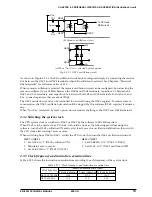
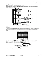
The E0C6006 has a built-in clock timer that uses the OSC1 oscillation circuit as the clock source. The clock
timer is configured as a 8-bit binary counter that counts with a 256 Hz source clock from the divider. The
8 bits of the counter (128 Hz–1 Hz) can be read by the software in 4-bit units.
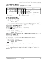
Figure 4.8.1.1 is the block diagram of the clock timer.
128 Hz–16 Hz
Data bus
32 Hz, 8 Hz, 2 Hz
256 Hz
Clock timer control signal
Oscillation
circuit
Interrupt request
Interrupt
control
8 Hz–1 Hz
Fig. 4.8.1.1 Block diagram of clock timer
Normally, this clock timer is used for all kinds of timing purpose, such as clocks.
Note: The information given in this section is based on f
OSC1
= 32.768 kHz. For a system which uses an
oscillator having any other frequency at OSC1, substitute the appropriate value for 32.768 kHz
throughout this section.
4.8.2 Interrupt function
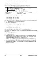
The clock timer can generate interrupts at the falling edge of the 32 Hz, 8 Hz, and 2 Hz signals. The
software can mask any of these interrupt signals.
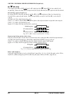
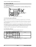
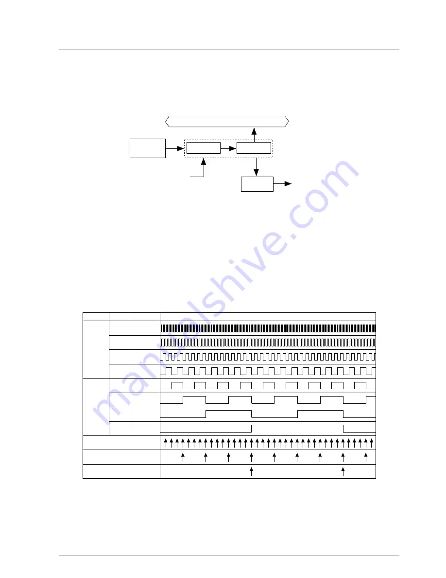
Figure 4.8.2.1 is the timing chart of the clock timer.
Address
0F4H
0F5H
32 Hz interrupt request
8 Hz interrupt request
2 Hz interrupt request
Bit
D0
D1
D2
D3
D0
D1
D2
D3
Frequency
Clock timer timing chart
128 Hz
64 Hz
32 Hz
16 Hz
8 Hz
4 Hz
2 Hz
1 Hz
Fig. 4.8.2.1 Timing chart of the clock timer
As shown in Figure 4.8.2.1, an interrupt is generated at the falling edge of the 32 Hz, 8 Hz, and 2 Hz
signals. At this point, the corresponding interrupt factor flag (IT32, IT8, IT2) is set to "1". The interrupts
can be masked individually with the interrupt mask register (EIT32, EIT8, EIT2). However, regardless of
the interrupt mask register setting, the interrupt factor flags will be set to "1" at the falling edge of their
corresponding signal (e.g. the falling edge of the 2 Hz signal sets the 2 Hz interrupt factor flag to "1").


