42
3.4. Puesta en marcha del Sistema P2S
3.4.1. Antes de conectar
Una vez realizado todo el proceso descrito en el punto
3.3
”, se detalla el proceso de puesta en
marcha. Si se ha llevado correctamente a cabo el
proceso de instalación descrito deberá encontrarse
todo de la siguiente manera. En caso contrario corríjalo.
Toda la alimentación del ascensor deberá
estar desconectada.
Todos los elementos correctamente
fijados.
Convertidor DC/DC, Cargador de baterías,
Inversor monofásico y Baterías cableadas
entre sí.
Todas las conexiones de tierra (Convertidor
DC/DC, Cargador de Baterías e Inversor)
debidamente cableadas. Se recomienda
comprobarlo con un multímetro. La
tensión de baterías deberá estar por
encima de 50V
Protección de baterías abierta (portusibles
abierto).
Interruptor “ON OFF” (
) del Convertidor
DC/DC en la posición OFF.
Los terminales “ENABLE INVERTER”
y
“GND”
del Convertidor DC/DC deben
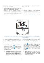
estar en circuito abierto. Ver
Error!
Reference source not found.
26
.
Interruptor ON/OFF (
) del inversor
monofásico en la posición OFF.
3.4.2. Proceso de conexión: IMPORTANTE
1)
Cablear los terminales
,
y
del Cargador de
baterías a la red monofásica (estando protegido por un
interruptor de corte aguas arriba de la conexión para
asegurar de una conexión segura). Esta será la única
toma de energía del ascensor ya que la única conexión
con la acometida es la del Cargador de baterías.
i)
11- Conexión a tierra
–
(FG).
ii)
12- Conexión AC (Fase)
–
(AC/L).
iii)
13- Conexión AC (Neutro)
–
(AC/N).
2)
Cierre el porta-fusible (ver
3.4. P2S System Start Up
3.4.1. Before connecting
Once “Installation” chapter has been completed; you
can proceed with the start-up steps. If you followed
each one of the installation steps, everything should
be found as follows. In any other case, fix it.
Elevator is disconnected from electric
mains.
Each element is well adjusted to the wall.
DC/DC converter, battery charger, single-
phase inverter and batteries are wired.
Each earth connection (DC/DC converter,
battery charger and single-phase
inverter) is properly wired. We
recommend
verifying
it
with
a
multimeter. Battery array voltage should
be more than 50V.
Fuse holder is open.
DC/DC converter “ON OFF” switch (
) in
OFF position.
DC/DC converter “ENABLE INVERTER”
terminals
and “GND”
must not
be shorted. See
Error! Reference source
not found.
26.
Single-phase inverter ON/OFF switch (
) in OFF position.
3.4.2. Connection procedure: IMPORTANT
1)
Wire batteries charger terminals
,
y
to
single-phase mains. This will be the only source of
energy consumption, as it is the only electric grid
connection (make sure the supply is shut down before
connecting).
i)
11- Earth connection
–
(FG)
ii)
12- AC (Phase) connection
–
(AC/L)
iii)
13- AC (Neutral) connection
–
(AC/N)
2)
3)
Tur
n ON DC/DC converter “ON OFF” switch (
).
4)
Connect the battery charger to the grid.
5)
Turn ON single-
phase inverter “ON/OFF” switch (
).
13
1
3
12
1
2
11
1
1
25
2
5
3A
3
A
3C
3
C
10
8
25
10
13
12
11
1
25
3A
3C
10
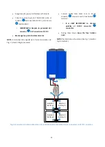
OBLIGATORIO Variador de
velocidad trifásico
380 - 400Vac
COMPULSORY Three-phase
frequency controller
380 - 400Vac
Содержание P2S Series
Страница 1: ...1 Manual de instalaci n Installation guide P2S Series plug single phase P2S powered by...
Страница 2: ...2 Versi n 4 6 June 2018 Epic Power Converters S L...
Страница 9: ...9 Fig 3 Convertidor DC DC 5k5 5k5 DC DC Converter 0 1 2 3 4 6 10 9 7 8 5...
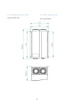
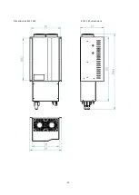
Страница 55: ...55 Dimensiones EPCL 5K5 EPCL 5k5 dimensions...
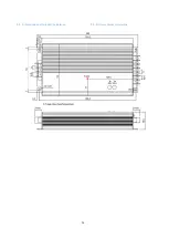
Страница 56: ...56 6 6 Dimensiones del cargador de bater as 6 6 Battery charger dimensions...
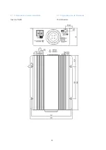
Страница 57: ...57 6 7 Dimensiones del inversor monof sico 6 7 Single phase inverter dimensions Inversor TS 400 TS 400 Inverter...
Страница 58: ...58 Inversor TS 700 TS 700 Inverter...
Страница 59: ...59 6 8 Dimensiones del Controlador de carga solar 6 8 Solar charge controller dimensions...
Страница 61: ...61 6 9 2 Bastidor bater as Small 4x1 6 9 2 Small batteries rack 4x1...
Страница 62: ...62 6 9 3 Bastidor bater as Medium 6 9 3 Medium batteries rack...


