background image


     ADVANCED FEATURES 


     Valve Delays 


189 | 

P a g e


Copyright © 2021 BF ENTRON and/or its affiliates. All rights reserved


Product Model: 

iPAK2v2 

Firmware Version: 

V2.10 

May 22 | Doc No 700253-2 

9.10.1


Programming Valve Delay Parameters using NetFlash 

Example 1

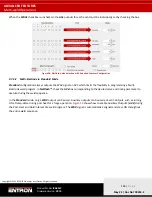
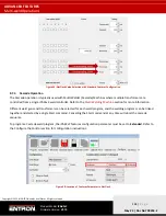
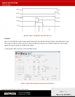
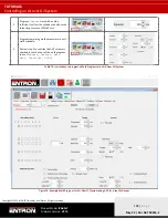
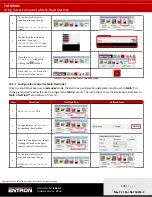
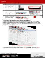
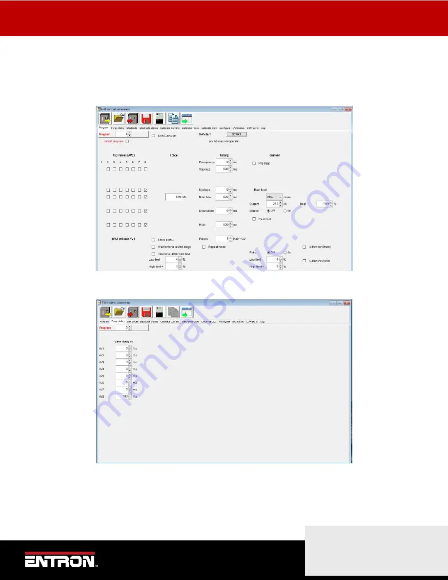
The AUX valve outputs can be programmed to activate after the start of any interval. In this example, NetFlash is used to 
program AV8 to come on 100 ms after the start of the main heat interval: 


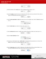
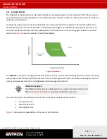
Figure 64: Example 1 NetFlash Program Valve Delay Selection Parameters 


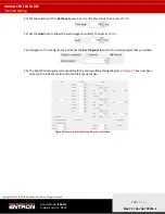
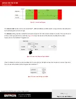
Figure 65: Example 1 Weld Program Forge Valve Delay Time Parameters 

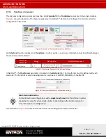
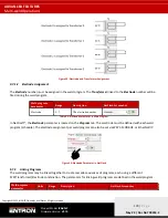
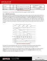
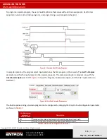
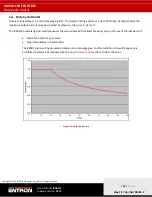
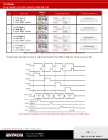
The resulting output is shown below in

 Figure 67

.


Содержание iPAK2v2

Страница 1: ...User Manual iPAK2v2 Weld Control Firmware Version V2 10 May 22 Document No 700253 2...

Страница 2: ...damage caused by improper installation use or application of its products The user shall only use the product for purposes that are proper and in accordance with all applicable laws rules and regulati...

Страница 3: ...Revisions Languages This document is only published in the English language Date Document Number Approved By Document Changes 14 01 2022 700253 0 Kelby Henn Initial release of iPAK2v2 Manual on new te...

Страница 4: ...es 14 2 3 Product Specifications 15 2 3 1 Power Specifications 16 2 3 2 Function and Monitoring Specifications 17 2 3 3 iPAK2v2 Weld Timer Specifications 17 2 3 4 Environmental Specifications 18 2 4 M...

Страница 5: ...US TCP IP 68 3 4 MODBUS RTU 69 3 5 WSP3 Pendant 71 4 ENTRON PROGRAMMING TOOLS 72 4 1 NetFlash 72 4 1 1 System requirements 72 4 1 2 Installing NetFlash 73 4 1 3 Removing NetFlash 73 4 1 4 Running NetF...

Страница 6: ...g 115 6 FAULTS TROUBLESHOOTING 116 6 1 Fault and Status Messages 116 6 2 LED Indicators on Timer 118 6 2 1 Heartbeat LED 118 6 2 2 Ready LED 119 6 2 3 Sequence LED 119 6 2 4 Weld LED 119 6 2 5 Data Se...

Страница 7: ...2 9 1 3 Viewing the Log 153 9 1 4 Exporting History Log 154 9 1 5 Resetting History Log 154 9 2 Security Settings 155 9 2 1 PIN Codes 156 9 2 2 Edit Switch 156 9 2 3 NetFlash User Security 157 9 3 Upd...

Страница 8: ...Electrodes 200 10 2 3 Program the WAV Output for Each Weld Program in the Cascade Sequence 201 10 2 4 Link Programs Together Cascade 203 10 3 Controlling a Multi Welder Cascade 205 10 3 1 Configure C...

Страница 9: ...orkplace per NFPA 70E or equivalent standard in your location This manual has been written for the iPAK2 MFDC weld control product line with an iPAK2v2 weld timer The manual applies to the V2 09 versi...

Страница 10: ...ution symbol indicates a hazard which could result in non life threating personal injury or damage to equipment CAUTION may also be used to alert against unsafe practices PACEMAKER Individuals with ca...

Страница 11: ...enclosure door when the breaker is in the ON position Never operate control with the door open Always disconnect power to the weld control before servicing or establishing electrical connections with...

Страница 12: ...nts where water will condense It is not recommended that holes be drilled into the cabinet Metal debris inside the cabinet can cause a short circuit electric shock or fire If holes must be drilled is...

Страница 13: ...or service and technical support we request that customers fill out the Technical Support Form found on our website at link below TECHNICAL SUPPORT FORM LINK https www entroncontrols com resources tec...

Страница 14: ...expulsion ie weld splash less likely High secondary current capability High speed constant current response Longer electrode life due to shorter weld times Requires smaller welding transformer size 2...

Страница 15: ...P or MODBUS RTU An iPAK2v2 weld control is also available in Multi Welder Cascade configurations This configuration type allows a user to control multiple weld transformers and multiple weld actuators...

Страница 16: ...60 Hz Output Current Options 20 Duty Cycle 360 A Water Cooled 600 A Water Cooled 1000 A Water Cooled 1500 A Water Cooled 3000 A Water Cooled 4500 A Water Cooled 6000 A Water Cooled DC BUS Levels at L...

Страница 17: ...Feedback Primary Current Range 36A to 360A 60A to 600A 100A to 1000A 150A to 1500A 300A to 3000A 450A to 4500A 600A to 6000A Timing Control Milliseconds Duty Cycle Limit 20 at rated capacity over 200...

Страница 18: ...ntal Specifications 2 3 4 1 Cooling Water Specifications Description Inverter Size Value Maximum Water Temperature All must not exceed 77 degrees Fahrenheit or 25 degrees Centigrade Water Quality All...

Страница 19: ...converts the 3 phase 380 480V 50 60 Hz AC line input into a 1kHz output high voltage AC square wave output to the welding transformer The unit is water cooled Circuit Breaker A 3 Phase thermal magneti...

Страница 20: ...03 10 00 10 58 30 10 01 03 10 00 10 58 C0 10 01 03 10 00 10 58 C0 10 01 13 10 01 10 58 40 10 01 03 10 00 10 58 41 00 01 03 10 00 iPAK2v2 360AWBv2 125ET 1SW iPAK2v2 600AWB 160ET 1SW iPAK2v2 600AWBv2 16...

Страница 21: ...ontrols com to request the drawing for your product Please include the following in your request your name company name part number and product serial number You can also visit www entroncontrols com...

Страница 22: ...ION Wiring Diagrams 22 P a g e Copyright 2021 BF ENTRON and or its affiliates All rights reserved Product Model iPAK2v2 Firmware Version V2 10 May 22 Doc No 700253 2 2 5 2 Wiring Diagram 3U3719 Figure...

Страница 23: ...odes The typical variants of standard machines are Standard pedestal machines Manual weld guns Robot guns Seam welders Below is a schematic showing an example of a single MFDC transformer connected to...

Страница 24: ...ers that are controlled by a single weld control There are two types of multi welding machines that are supported by the iPAK2v2 weld timer Multi Head Machine A Multi Head machine has up to 8 valves a...

Страница 25: ...ransformer executes a weld in a sequence or cascading manner This is why this type of machine is typically referred to as a Cascade A Multi Welder Cascade weld control requires additional SCRs to cont...

Страница 26: ...Primary Current setting from 0 to 99 9 0 99 9 Max Primary Current Heat Percent Max Primary Current Primary or Secondary Regulation 0 2 99 9 1 CCC Constant Current Calibrated The control regulates the...

Страница 27: ...heat 2 8 2 Constant Current Uncalibrated Mode CCu Constant Current Uncalibrated CCu mode uses a variable pulse width to determine and regulate the actual current The current and heat parameters are in...

Страница 28: ...ubmit a claim with the shipper a If the shipping terms are FOB Origin or Ex Works the claim should be submitted by the receiver b If the shipping terms are the responsibility of the seller the claim s...

Страница 29: ...Always follow your local regulations and facility procedures for locking out electrical connections Always verify power is OFF before wiring control 5 Mount the Control Mount the control in the desir...

Страница 30: ...lines to the water manifold The standard configuration has the water manifold located on the left hand side of the cabinet 9 Test Water Connections Turn on the water cooling circuit and verify there a...

Страница 31: ...electrical connections inside the cabinet to verify connections are tight and secure 14 Close and Lock Door Close the cabinet door Using the provided key rotate the sealing mechanism to seal the cabi...

Страница 32: ...ing control to your required resistance welding process See the Configure the Control section for more details 22 Set the IP Address of the Control Set the IP address of the control following the proc...

Страница 33: ...xtended 2nd Stage Contactor Stop on Fault EOS on Fault Headlock on Fault iPAK v1 Mode Measure Regulation Toroid Test Units Program Select Analog Output Current Limit Retract I O Source Local Security...

Страница 34: ...e restarted for this change to take effect Value Description Standard Default setting with basic features This is selected for spot spot repeat and projection welding applications It is typically used...

Страница 35: ...The 2nd stage input is checked before the Squeeze interval The motor output is activated when 2nd Stage input is confirmed The Motor Output is only used for Seam Welding applications After Squeeze Th...

Страница 36: ...are used for Multi Welder Cascade selection This flag may be needed when an iPAK or iPAK MUX is updated to an iPAK2 timer in the field 2 9 2 8 Measure The Measure parameter determines which current v...

Страница 37: ...ram parameter selects the weld program This can be set by Netflash or WSP3 Hand Held Pendant 2 9 2 13 Analog Output 0 to 10V The Analog Output parameter defines what signal the control will output on...

Страница 38: ...onents in the system For example a seam welder may need to work with continuous currents In this case the control must be set to a primary maximum or below the duty cycle rating 2 9 2 15 Retract The R...

Страница 39: ...t a security function that prevents all users from changing the parameters When the security feature has been enabled all parameters are Read Only to users who do not have the security code or key The...

Страница 40: ...No 700253 2 2 9 2 19 Factory Reset The control parameters can be set to the default values by clicking the Initialise action button The iPAK2v2 must be restarted for this change to take effect CAUTIO...

Страница 41: ...ctrical circuit and output a constant current The iPAK2v2 system is designed for precision and the output highly repeatable The calibration procedure increases the accuracy of the regulation and actua...

Страница 42: ...Primary Current 2 Set Turns Ratio to the transformer Turns Ratio Set Turns Ratio to the transformer Turns Ratio 1 2 Point CT Calibration Set Turns Ratio to the transformer Turns Ratio Set Turns Ratio...

Страница 43: ...control 3 Open the NetFlash software application on a computer and connect to the target control 4 Load the parameters from the target control by clicking the Load From Control Icon 5 Navigate to the...

Страница 44: ...ENTRON and or its affiliates All rights reserved Product Model iPAK2v2 Firmware Version V2 10 May 22 Doc No 700253 2 11 If the Restart Required message is present restart the control by cycling the p...

Страница 45: ...cedure for setting the turns ratio using NetFlash is 1 Determine the Turns Ratio from the welding transformer data sheet or transformer product label 2 Connect the computer to the control via an Ether...

Страница 46: ...ndary current from the measured primary current Figure 13 Point 1 2 CT Calibration Diagram To calibrate the built in CT sensor using the Point 1 2 method follow the steps defined below 1 Get an extern...

Страница 47: ...The output of the weld control will be a equivalent of Heat input 10 Produce a short circuit weld 11 Note the following values Ip1 Primary Weld Current 1 viewed in the Log tab or displayed on the WSP...

Страница 48: ...on of Internal CT 17 Enter the Ip1 Ip2 Is1 and Is2 values into the table as shown below 18 After updating each of the Ip1 Ip2 Is1 and Is2 values press Enter or Tab after each field change to update th...

Страница 49: ...e iPAK2v2 is as follows 1 Turn Off the iPAK2v2 weld control 2 Install the Toroid Rogowski coil around the welding transformer secondary 3 Connect the Toroid Rogowski coil to the iPAK2v2 via Connector...

Страница 50: ...e Factor signal based on the expected Secondary Current a If the current is not expected to exceed 50 kA then set the factor to 1 b If the current is expected to exceed 50 kA then the factor should be...

Страница 51: ...Current tab 21 Adjust the Sensitivity value accordingly If the readings are not close adjust the Sensitivity value based on the equation below Sensitivity Control reading 150 Meter Reading 22 Repeat...

Страница 52: ...C Diagram Projection Welding Performance CCC Calibration should be done for Projection Welding applications CCC Calibration increases the rise time to the target current without causing any significan...

Страница 53: ...wing values H1 Heat target from the Program tab Is1 weld current from the Log tab in NetFlash or current displayed on the WSP3 pendant 9 For the active weld program set the Heat value to a higher valu...

Страница 54: ...le 24 After updating each of the Ip1 Ip2 Is1 and Is2 values press Enter or Tab to push the change to the control 25 The CCC Calibration procedure is now complete The iPAK2v2 unit can be programmed in...

Страница 55: ...the computer to the control via an Ethernet cable 2 Turn ON the iPAK2v2 weld control 3 Open the NetFlash software application on computer and connect to the target control 4 Load the parameters from...

Страница 56: ...The calibration is based on a two point lookup table and requires a weld force gauge The weld force can be calibrated in terms of kN or lbf The units of measure are defined in the configuration secti...

Страница 57: ...ong the 0 to 10 V range The actual force values will be dependent on actuator used to generate force Programmed Force kN Programmed Force lbf Output Voltage WSP3 Output Voltage NetFlash V 0 00 0 0 mV...

Страница 58: ...or the first reading 5 Navigate to the I O status tab and locate the analog readings 6 Initiate a weld and document the following values during the weld a The weld force reading form the gauge b The A...

Страница 59: ...eserved Product Model iPAK2v2 Firmware Version V2 10 May 22 Doc No 700253 2 10 Repeat Steps 4 9 to get a reading for the remaining point of the lookup table WELD OFF Always verify the iPAK2v2 is in We...

Страница 60: ...tions Verify water follow is appropriate for inverter module Quarterly ON Cabinet Inspect cabinet for damage or deterioration Annually ON Cabinet Doors Verify doors operate and verify the door properl...

Страница 61: ...signed to communicate with external devices such as PLCs with standard communication protocols for industrial systems This section of the manual describes how to configure the iPAK2v2 weld control to...

Страница 62: ...rt supports I O data exchange and welding programming parameters via MODBUS communication 3 2 Set the IP Address of the Control The IP Address is critical for communication with external devices The i...

Страница 63: ...tion icon to open the Networking window 5 If the control is not known by the PC click the Scan Network for Controls icon to find the control Control Not Found If the control is not recognized by the P...

Страница 64: ...ol has now been modified The control must be restarted When you using Netflash the control will automatically be restarted upon IP Address change 9 Now that the control is known by the PC the IP Addre...

Страница 65: ...Ethernet Standard Ethernet 503 30718 The Ethernet port provides standard communication of I O data exchange and welding programming parameters This port is typically used for interfacing with the NetF...

Страница 66: ...rols icon to find the control Control Not Found If the control is not recognized by the PC make sure the firewall does not block Ethernet ports 503 and 30718 used for NetFlash 6 Select the desired con...

Страница 67: ...e of the control s input must be mapped to COM6 E IP The steps to configure the I O source to COM6 E IP using the NetFlash software are below The configuration parameters can also be set via WSP3 hand...

Страница 68: ...s input must be mapped to COM5 The steps to configure the I O Source to COM5 using the NetFlash software are defined below The configuration parameters can also be set via WSP3 handheld pendant 1 Con...

Страница 69: ...in Figure 20 Figure 20 iPAK2v2 Control RS485 Port To have the welding control use the MODBUS RTU data and activate the inputs the I O source of the control s input must be mapped to COM2 The steps to...

Страница 70: ...Product Model iPAK2v2 Firmware Version V2 10 May 22 Doc No 700253 2 7 Restart the control for the I O source field change to take effect by clicking the Restart control icon 8 Connect the remote MODBU...

Страница 71: ...unicate with a WSP3 Pendant The steps for connecting the WSP3 Pendant to the iPAK2v2 are as follows 1 Connect the WSP3 Pendant to the iPAK2v2 weld control via a RS232 cable 2 Turn ON the iPAK2v2 weld...

Страница 72: ...iptor files which each control type serves up to NetFlash describing how the UI should appear When changes are made to a control e g the addition of a new feature its descriptor is updated to reflect...

Страница 73: ...To remove NetFlash delete the NetFlash folder and its contents from the PC 4 1 4 Running NetFlash Open the installation folder and run NetFlash exe The Main window will open If the security function i...

Страница 74: ...act information Edit Control Parameters Opens the Edit Parameters window for control configuration calibration and weld programs Network Configuration Opens the Networks window Restart Control Restart...

Страница 75: ...n the window is open and data is loaded the Control ID shows the source An icon is used to indicate the source of the data data source is a file data source is a control Communication Status Indicates...

Страница 76: ...g key configuration parameters CAUTION ACUTATOR MOTION Use CAUTION when clicking the restart control icon when the control is in use The restart function will reset the value outputs which can cause u...

Страница 77: ...w The Networks window can be viewed by clicking on the tool bar button on the main screen The window contains tools for managing and accessing controls on the network It allows controls to be assigned...

Страница 78: ...will search the connected network and report a list of controls found To assist with identification both the IP address and MAC number are reported Click on any control in the list then click OK to se...

Страница 79: ...el iPAK2v2 Firmware Version V2 10 May 22 Doc No 700253 2 4 1 10 Edit Control Parameters The Edit Control Parameters window can be viewed by clicking on the Edit Control Parameters button on the main s...

Страница 80: ...e interface and all data to a file on the PC A browsing window will open and you will be prompted for a file name and location Can be used as part of a backup restore process or for transferring setti...

Страница 81: ...A spinner allows the parameter to be incremented or decremented by 1 unit by clicking on the up arrow or down arrow A new value for the parameter can also be entered by first highlighting the paramet...

Страница 82: ...le name and location All subsequently received records will be written to this file Stop Recording Log Data to File Stops recording log data to file Clear Screen Clicking this button will clear the lo...

Страница 83: ...ramming Tool The Flash Programming Tool window can be viewed by clicking on the tool bar button on the main screen This window is used to Get information about the target control Update firmware in th...

Страница 84: ...k Open The filename will now appear at the top of the Flash Window Start Transfer to Control Click on this tool to begin the firmware transfer to the control You will be prompted to choose which memor...

Страница 85: ...10 May 22 Doc No 700253 2 4 1 14 Setup NetFlash Users Security The Security window can be viewed by clicking on the tool bar button on the main screen This window is used to 1 Configure user s names p...

Страница 86: ...n existing user Click on the user in the table then click the tool Edit Existing User Edits information for an existing user Click on the user in the table then click the tool A dialog opens showing t...

Страница 87: ...ccess diagnostic information and set all parameters in the weld control The WSP3 uses RS232 to communicate with the iPAK2v2 and should be connected to the COM3 port on the timer Complete controls typi...

Страница 88: ...een is the default screen for the WSP3 and displays error messages and the measured values of the last executed weld program To navigate to the Diagnostic Screen press the F key until you reach the di...

Страница 89: ...e program parameters status information configuration settings system information and history log The current menu is shown at the top of the screen inside the chevron symbols menu name The menu tree...

Страница 90: ...u to build your unique weld program schedule Resistance welding is a process that fuses two pieces of metal using the electrical property of resistance to create a weld Resistance welding does not req...

Страница 91: ...nts Hold Time Hold time is the time during which electrode force is maintained after the last impulse of weld current This phase is necessary to allow the weld nugget to solidify before the weld force...

Страница 92: ...eld program will re run if a Low Main Current is detected This function should only be selected for spot welding C Monitor shunt2 ON OFF The measured conduction will be checked against the C monitor s...

Страница 93: ...nt Post heat3 0 1999 ms The time the post heat welding current is applied Hold 0 1999 ms The time the electrode force continues after the welding current has finished Off4 0 1999 ms Electrode force is...

Страница 94: ...9 9 The heat used during the Main heat interval in PHA mode Main current kA 0 00 500 The current used during the Main heat interval in CCC mode Set point for monitoring Main Monitor YES NO Enables mon...

Страница 95: ...he start the Hold interval Wait for force 2 YES NO Wait until the applied force has been reached Test force YES NO Test the applied force at the end of the Main interval Low limit 0 99 Force low limit...

Страница 96: ...V output Motor 1 AV1 AV8 Motor output Squeeze AV1 AV8 off 1 8 on Valve starts during the Squeeze interval Pre heat AV1 AV8 off 1 8 on Valve starts during the Pre heat interval Cool 1 AV1 AV8 off 1 8 o...

Страница 97: ...mmon resistance welding types that the iPAK2v2 supports spot welding spot pulsation spot repeat seam roll spot welds A weld sequence is provided for each of these common welds to give the user an idea...

Страница 98: ...at current in a controlled manner 6 The post heat is weld current is applied Typically used to control the solidification of the weld nugget and minimize cracking 7 A hold is used to allow the weld nu...

Страница 99: ...fined below 1 Pre squeeze and squeeze time for the actuator to reach the desired weld force 2 An upslope pulse is used to ramp the weld current to the main current in a controlled manner 3 The first p...

Страница 100: ...e set as follows Parameter OPTIONS Value Program Inhibit NO Pre Heat NO Post heat NO Pulsations 1 Link NO Repeat Mode YES Force Profile NO Retry OFF C Monitor OFF C Monitor OFF Table 31 Pulsation Spot...

Страница 101: ...in difference being that the welding wheel electrodes are motor driven rather stationary electrodes Figure 31 shows a typical timing diagram for a seam weld To use seam welding Mode the configuration...

Страница 102: ...pulse is executed to ramp the current to the main heat in a controlled manner 7 The Main heat current pulse is executed followed by the Cool2 sequence 8 The Main heat current and Cool2 pulse is repeat...

Страница 103: ...ot Weld Timing Diagram The weld program options are set as follows Parameter Value Pre Heat Off Post heat Off Pulsations 1 Force Profile Off Repeat On Table 35 Roll Spot Weld Timing Diagram Weld Optio...

Страница 104: ...program schedule The skills learned in this section can be built upon to create a weld program for your unique resistance welding application This section assumes that the control has been installed c...

Страница 105: ...the WSP3 Step Description Screen Parameters Key Inputs 1 Turn ON the iPAK2v2 Weld Control 2 The Status Screen will be displayed on the WSP3 3 Press the F key to navigate to the Main Menu To Enter Men...

Страница 106: ...T NO HEADLOCK NO IPAK v1 MODE NO PROG SELECTION INTERNAL RETRACT SIMPLE I O SOURCE DISCRETE ANALOG CONTROL OFF ANALOG OUT FORCE WAVE FORM 10V 30 0 kA CONTACTOR 0 s COM2 RS485 COM3 RS232 ETHERNET BACKU...

Страница 107: ...o scroll 12 After all TIMING parameters have been set press F key to return to the program menu 13 Scroll down using the Down Arrow key to EDIT CURRENT option and press Return key To Scroll Down Use t...

Страница 108: ...16 If using a Proportional Valve Regulator Scroll down using the Down Arrow key to EDIT FORCE parameters press Return key To Scroll Down To Enter Menu 17 Scroll down using the Down Arrow key and the...

Страница 109: ...user to inhibit the program from running if not required Enable the pre heat parameter pulse the current in weld enable repeat welding if required To return to the Timer Status screen press the F key...

Страница 110: ...he NetFlash software This example provides an overview of the process for programming a weld program schedule The skills learned in this section can be built upon to create a weld program for your uni...

Страница 111: ...May 22 Doc No 700253 2 Figure 34 Simple Spot Weld Timing Diagram Live Data Update When connected to a control updates to control parameters occur on a field change in NetFlash For checkboxes and arrow...

Страница 112: ...rify the iPAK2v2 is configured for a spot weld on a standard machine Configuration Parameter Value Features Standard Weld Type Spot Retract Off Simple I O Source Discrete 2nd Stage Off Regulation Seco...

Страница 113: ...12 Since we are controlling the heat in P W mode the magnitude of the weld pulse is set in terms of Heat Set this value to your desired Heat 13 Set the duration of the Cool1 pulse in terms of Millise...

Страница 114: ...the Downslope value in terms of milliseconds This defines the time the control will take to ramp down from the Main Heat Current to the Post heat current 20 Set the Hold time to allow the weld nugget...

Страница 115: ...n be set manually in NetFlash in the Configure Tab or via the WSP3 pendant Figure 36 Use Program Field in NetFlash 5 7 2 External Program Selection The External Program selection requires the Program...

Страница 116: ...the iPAK2 and return it for service Restart required Restart the iPAK2 Headlocked The welding head is locked because of a fault condition Toroid short circuit Connection to Toroid secondary feedback c...

Страница 117: ...5 Reset counter 5 End of count 6 Reset counter 6 End of count 7 Reset counter 7 End of electrode 0 Reset stepper 0 End of electrode 1 Reset stepper 1 End of electrode 2 Reset stepper 2 End of electrod...

Страница 118: ...Indicators on Timer The iPAK2v2 weld timer has an array of LED lights that indicate activity and status information LED FUNCTION MS EtherNet IP module status NS EtherNet IP network status 1 Heartbeat...

Страница 119: ...onds signals for the COM ports numbered 2 through 5 The Send LEDs are defined with odd numbers The Receive LEDS are defined by even numbers When communications are being sent or received the LED will...

Страница 120: ...uick way to clear the messages directly at the machine When on the Diagnostic screen the fault conditions and error message with at the top of the screen will rotate through all messages To clear the...

Страница 121: ...r Description Reset fault P2 15 This input resets the Fault output and clears the status messages Only momentary application is required minimum time 40ms 6 3 4 Fieldbus Input The EtherNet IP and MODB...

Страница 122: ...eld sequence begins If the input is removed during the Squeeze interval the sequence is aborted If the input is maintained through the Squeeze interval but switched off subsequently the sequence termi...

Страница 123: ...rograms 0 to 63 can be selected programs 64 to 255 can still be selected internally or via the fieldbus P2 P2 7 BP2 P4 P2 8 BP4 P8 P2 9 BP8 P16 P2 10 BP16 P32 P2 11 BP32 P64 Edit enable 5 P2 17 BP64 P...

Страница 124: ...tput is active if iPAK2v2 is ready to weld The output switches off under some fault conditions Contactor P3 17 MC1 This output can be used to control an isolation contactor Counter tip dress request P...

Страница 125: ...analog inputs and outputs The analog connections can be used for monitoring analog signals such a toroid Rogowski coil controlling an external device such as a proportional valve or outputting a contr...

Страница 126: ...rtional air regulation valve The force must be calibrated Refer to the Force Calibration section for instructions For Current Waveform the analog output of the iPAK2v2 must be set to Current Waveform...

Страница 127: ...t practical in robotic cells or with machines where a PLC controls a gun or press It can be used during testing or calibration routines where the weld program needs to be executed remotely When using...

Страница 128: ...des full data exchange with any standard EIP devices For information on how to configure and connect the iPAK2v2 control for your desired communication protocol refer to the COMMUNICATIONS SETUP secti...

Страница 129: ...BOOL Reset counter Bit 7 QX0 7 BOOL Reset stepper Bit 8 QX1 0 BOOL Reserved Bit 9 QX1 1 BOOL Reserved Bit 10 QX1 2 BOOL Reserved Bit 11 QX1 3 BOOL Reserved Bit 12 QX1 4 BOOL Reserved Bit 13 QX1 5 BOO...

Страница 130: ...1 IX0 1 BOOL Fault Bit 2 IX0 2 BOOL Ready Bit 3 IX0 3 BOOL Contactor Bit 4 IX0 4 BOOL Counter Bit 5 IX0 5 BOOL Stepper Bit 6 IX0 6 BOOL Pre warn Bit 7 IX0 7 BOOL AV8 Bit 8 IX1 0 BOOL AV7 Bit 9 IX1 1...

Страница 131: ...13 IX5 5 BOOL Reserved Bit 14 IX5 6 BOOL Reserved Bit 15 IX5 7 BOOL Analog input mV Read outputs 3 IW6 WORD READ 16 9003 36867 Analog output mV Read outputs 4 IW8 WORD READ 16 9004 36868 pulse width R...

Страница 132: ...High force Bit 1 IX20 1 BOOL Bit 33 Low pre current Bit 2 IX20 2 BOOL Bit 34 High pre current Bit 3 IX20 3 BOOL Bit 35 Low main current Bit 4 IX20 4 BOOL Bit 36 High main current Bit 5 IX20 5 BOOL Bi...

Страница 133: ...BOOL Bit 70 End of electrode 7 Bit 7 IX24 7 BOOL Bit 71 Reserved Bit 8 IX25 0 BOOL Reserved Bit 9 IX25 1 BOOL Reserved Bit 10 IX25 2 BOOL Reserved Bit 11 IX25 3 BOOL Reserved Bit 12 IX25 4 BOOL Reserv...

Страница 134: ...READ 16 900C 36876 End of electrode 0 Bit 0 IX24 0 BOOL Bit 64 End of electrode 1 Bit 1 IX24 1 BOOL Bit 65 End of electrode 2 Bit 2 IX24 2 BOOL Bit 66 End of electrode 3 Bit 3 IX24 3 BOOL Bit 67 End...

Страница 135: ...t 6 IX28 6 BOOL Bit 102 Prewarn 7 Bit 7 IX28 7 BOOL Bit 103 Reserved Bit 8 IX29 0 BOOL Reserved Bit 9 IX29 1 BOOL Reserved Bit 10 IX29 2 BOOL Reserved Bit 11 IX29 3 BOOL Reserved Bit 12 IX29 4 BOOL Re...

Страница 136: ...53 2 Variable Channel Address Type Description Main current A Read outputs 18 IW36 DWORD READ 16 9012 36882 Post heat current A Read outputs 20 IW40 DWORD READ 16 9014 36884 Program number Read output...

Страница 137: ...WORD ARRAY 0 63 Weld program 254 16 3F80 16256 WORD ARRAY 0 63 Weld program 255 16 3FC0 16320 WORD ARRAY 0 63 Weld program extensions 256 x 16 WORDS Weld program 0 extension 16 7000 28672 WORD ARRAY 0...

Страница 138: ...864 WORD ARRAY 0 63 Calibration 7 16 51C0 20928 WORD ARRAY 0 63 Configuration 1 x 64 WORDS Configuration 16 6000 24576 WORD ARRAY 0 63 Table 51 Modbus Programming Parameters CAUTION Modbus users updat...

Страница 139: ...arameter s address Start address 0000 Weld program number x 64 Parameter address offset in Weld program For example to obtain the address of Main current of weld program 5 calculation will be Start ad...

Страница 140: ...d program 15 IW15 WORD 1 99 Post heat time Weld program 16 IW16 WORD 0 1999 Post heat Weld program 17 IW17 WORD 0 999 x10 Reserved Weld program 18 IW18 WORD Post current Weld program 19 IW19 DWORD 0 5...

Страница 141: ...mit Weld program 46 IW46 WORD 0 99 Selected WAV Weld program 47 IW47 WORD 0 7 Current low limit Weld program 48 IW48 WORD 0 99 Current high limit Weld program 49 IW49 WORD 0 99 Selected electrode Weld...

Страница 142: ...appropriate delay parameter Variable Channel Address offset Type Description Weld program extension IW0 WORD ARRAY 0 15 AV1 delay time Weld program extension 0 IW0 WORD 0 9999 AV2 delay time Weld pro...

Страница 143: ...rts at address 16384 16 4000 and ends at address 16447 16 403F then each subsequent schedule uses next 64 words addresses with the electrode 7 s data using address 16832 16895 16 41C0 41FF The address...

Страница 144: ...count Bit 3 IX0 3 BOOL 0 off 1 on Stop at endstep Bit 4 IX0 4 BOOL 0 off 1 on Transformer Electrode 1 IW1 WORD 0 7 Counter Electrode 2 IW2 WORD 0 9999 Endcount Electrode 3 IW3 WORD 0 9999 Dressings do...

Страница 145: ...6 5000 and end at address 20543 16 503F then each subsequent Calibration parameter set uses next 64 words addresses with electrode 7 s data using address 20928 20991 16 51C0 51FF The address offset of...

Страница 146: ...00 mV A in Y2 Calibration 8 IW8 WORD 0 32767 Reserved Calibration 9 IW9 WORD Toroid sensitivity Calibration 10 IW10 WORD 1 60000 mV kA Convert CT Calibration 11 IW11 WORD 0 use 2 points 1 use turns ra...

Страница 147: ...e 10 after Squeeze Bit 2 IX1 2 BOOL Reserved Bit 3 IX1 3 BOOL 0 check first program 1 check every program Retract Configuration 2 IW2 WORD 0 simple 1 hilift plus 2 hilift minus 3 maintained Measure Co...

Страница 148: ...2 Configuration 23 IW23 WORD 1000 9999 Security PIN2 2 Configuration 24 IW24 WORD 1000 9999 Security PIN3 2 Configuration 25 IW25 WORD 1000 9999 Security PIN4 2 Configuration 26 IW26 WORD 1000 9999 IP...

Страница 149: ...2 control uses Implicit messaging for Inputs outputs control status data exchanging with other EtherNet IP devices To communicate with the iPAK2v2 control through Implicit message the controlling devi...

Страница 150: ...e Service Code Class Code Instance Code Attribute Code Standard EtherNet IP protocol offers many Service codes for different Explicit message 8 3 2 1 Service Codes For control data setting exchange th...

Страница 151: ...gram ranging from 0 to 255 Refer to Table 52 to Table 56 for the Data Structure definitions 1 Get the weld program parameter in p by send the explicit message below Service Code 0E hex Class Code 96 h...

Страница 152: ...e The force measured during the weld Pulse width Conduction The conduction measured during the weld Table 57 History Log Data Structure The configuration of the iPAK2v2 determines which value current...

Страница 153: ...og Step Description Screen Parameters Key Inputs 1 From the Status Screen press the F key to go to the MAIN MENU 2 Scroll to the HISTORY LOG option using the Down arrow and press the RETURN key To Scr...

Страница 154: ...read from the Output after each weld Refer to the Outputs section for information Variable Channel Address Type Description Pre heat current A Read outputs 16 IW32 DWORD READ 16 9010 36880 Main curre...

Страница 155: ...ear log Pres to confirm clear log to Abort OR To Confrim 9 2 Security Settings The iPAK2v2 has security settings that can be enabled to prevent unauthorized users from updating parameters on the iPAK2...

Страница 156: ...he Local Security section open the dropdown for the Enable parameter and select PIN WSP3 4 The Timeout and PIN fields will appear Populate these as desired 9 2 2 Edit Switch An external Edit Switch ca...

Страница 157: ...ng none some or all of the parameters as required Thus an administrator can setup security in their installation of NetFlash and then can distribute copies of NetFlash to various personnel each having...

Страница 158: ...the control The user can toggle between the two memories without having to reprogram the firmware The BIOS memory stores the factory defaults Memory Description A Memory A B Memory B BIOS BIOS memory...

Страница 159: ...10 May 22 Doc No 700253 2 6 Click the Start transfer to control icon and select a memory to reprogram Select Memory to update You should then see Followed by When complete you will see the following...

Страница 160: ...r using either the WSP3 Pendant or the NetFlash software The backup file contains the configuration and all weld programs stored the iPAK2v2 CAUTION Unique IP Addresses Required The Backup Restoration...

Страница 161: ...d to any iPAK2v2 control via the WSP3 Step Description Screen Parameters Key Inputs 1 From the Status Screen press the F key to go to the MAIN MENU 2 Scroll to the EDIT CONFIGURATION option using the...

Страница 162: ...ss the F key to return to the CONFIGURE menu CONFIGURE 25 NOV 2021 11 23 19 FEATURES EXTENDED WELD TYPE SPOT 2nd STAGE OFF 2nd STAGE ONCE MEASURE PRIMARY REGULATION PRIMARY TOROID TEST OFF UNITS METRI...

Страница 163: ...tore a control with a the WSP3 follow the steps defined below Step Description Screen Parameters Key Inputs 1 From the Status Screen press the F key to go to the MAIN MENU 2 Scroll to the EDIT CONFIGU...

Страница 164: ...the F key to return to the CONFIGURE menu CONFIGURE 25 NOV 2021 11 23 19 FEATURES EXTENDED WELD TYPE SPOT 2nd STAGE OFF 2nd STAGE ONCE MEASURE PRIMARY REGULATION PRIMARY TOROID TEST OFF UNITS METRIC...

Страница 165: ...ntrol with the NetFlash software 2 Click the Load from control icon 3 Click the Save icon to open the Windows Explorer window 4 Save the file to your desired location Offline Development NetFlash can...

Страница 166: ...set to Extended for the iPAK2v2 to be capable of being is configured for a Multi Welder Machine The stepper and counter can be assigned to eight transformers When a program is run the iPAK2v2 will aut...

Страница 167: ...ep Heat1 0 0 50 0 The increase in heat during the step Current2 0 0 50 0 The increase in current during the step Preset 1 5 Apply predefined values to the stepper curve Enable stepper on off Enables o...

Страница 168: ...rease in current during the step Preset 1 5 Apply predefined values to the stepper curve Enable stepper on off Enables or disables the stepper Stop at end on off iPAK2v2 can inhibit welding at the end...

Страница 169: ...9 5 1 2 Preset Values To expedite programming the NetFlash software has preset values to populate the stepper table with initial values In the Electrode Tab on NetFlash Click on the P1 P2 P3 P4 or P5...

Страница 170: ...ings 0 9999 The maximum number of times the electrodes can be dressed Reset to welds 0 9999 The weld count following a tip dress operation Table 61 Electrode Counter Parameters in NetFlash Parameter U...

Страница 171: ...calibration procedure Toroid Rogowski coil on Multi Electrode System For a multi welder or multi head configuration it is not recommended that secondary measuring be performed using a toroid Rogowski...

Страница 172: ...Seam Weld with NetFlash This section provides an overview of how to program a simple seam weld program using the NetFlash software This example provides an overview of the process for programming a we...

Страница 173: ...with a keyboard entry the user must press Enter or Tab after a field change to push the data to the control The steps to program the Weld Program in Figure 47 are as follows 1 Open the NetFlash applic...

Страница 174: ...function by clicking the checkbox 7 Enable the Post heat function by clicking the checkbox 8 Set the Force value to your desired value then press ENTER 23 Set the Presqueeze value to the desired value...

Страница 175: ...e Main Heat Mode to P W mode where the current is programmed in terms of Heat then press ENTER 16 Set the Main Heat value in term of percent then press ENTER 17 Set the Main heat parameter in millisec...

Страница 176: ...rms of milliseconds then press ENTER 22 Set the Hold time to allow the weld nugget to solidify then press ENTER 23 Navigate to the Configure tab and verify the Use Program field is to the weld program...

Страница 177: ...to 8 Electrode Transformer pairs o Command up to 8 Weld Air Valves WAV1 WAV8 to close during a weld program Cascade operation allows the welding programs to be linked together and triggered from a si...

Страница 178: ...p must be defined between the electrode and transformer Electrode Parameter Range Description NetFlash Screenshot Transformer 0 7 The transformer that the electrode is connected to Table 64 Transforme...

Страница 179: ...Screenshot Electrode 0 7 The electrode number Table 65 Electrode Parameter in Weld Program In NetFlash the Electrode parameter is located on the Program tab The electrode must be defined with each we...

Страница 180: ...ctrode weld timing sequence A different weld program can be actuated on a different electrode or weld gun using a single transformer The WAV signal can use a different output for each program The STAR...

Страница 181: ...lti weld Operations 181 P a g e Copyright 2021 BF ENTRON and or its affiliates All rights reserved Product Model iPAK2v2 Firmware Version V2 10 May 22 Doc No 700253 2 Figure 56 Location of Features Pa...

Страница 182: ...sing One or More Weld Air Valves Extended mode is required when using one or more Weld Air Valves on a Multi Electrode Multi Gun machine Extended configuration allows a user to output the WAV signal o...

Страница 183: ...d configuration always outputs the WAV signal on AV1 which limits the flexibility in programming a Multi Electrode weld program In NetFlash check the AVx box corresponding to the desired valve and tim...

Страница 184: ...rs are controlled from a single iPAK2v2 weld controller Refer to the Multi Welding Machine section for more information Different weld guns and transformers can be selected for each weld program and t...

Страница 185: ...rogram in the cascade The Link To Program parameter specifies the next program in the cascade sequence The cascade ends when a program runs with the Link Cascade Option set to Off Figure 62 shows the...

Страница 186: ...ack To use Analog Control Mode the feature parameter must be set to Extended and the Weld Type parameter must be set to Analog in the configuration settings See the Configure the Control section for m...

Страница 187: ...nation of AV1 to AV8 may be selected Seam Single electrode AV1 AV2 AV1 and AV2 are automatically selected Seam Multi electrode AV1 AV8 AV1 AV8 Any combination of AV1 to AV8 may be selected Table 69 Co...

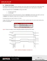
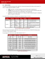
Страница 188: ...to the function An on delay may be applied to any of the AUX valves The delay is triggered when a valve is programmed to turn on at the start of any interval The actual turn on time is delayed by the...

Страница 189: ...rameters using NetFlash Example 1 The AUX valve outputs can be programmed to activate after the start of any interval In this example NetFlash is used to program AV8 to come on 100 ms after the start...

Страница 190: ...in use Example 2 Extra care should be taken when using pulsation welding as the program schedule contains a loop Main heat Cool2 Main heat Cool2 etc If the valve turn on point lies within the loop be...

Страница 191: ...ts affiliates All rights reserved Product Model iPAK2v2 Firmware Version V2 10 May 22 Doc No 700253 2 Figure 68 Example 2 Weld Program Forge Valve Delay Time Parameters The resulting output is shown b...

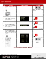
Страница 192: ...ss the F key to navigate to the Main Menu To Enter Menu 3 Scroll down to the Edit Program line using the Down arrow then press RETURN key To scroll Down To Enter Menu 4 Select correct Program number u...

Страница 193: ...n arrow to Edit Valve Delays and Press RETURN key To scroll Down To Enter Menu 9 Scroll using down arrow to AV8 DELAY Use and key to enter desired delay value eg 100 ms The AV8 valve will be turned on...

Страница 194: ...ack up Currents outside the weld lobe will have quality defects such as expulsion or the weld nugget is below the minimum weld size Figure 70 shows an example of a weld lobe diagram Figure 70 Weld Lob...

Страница 195: ...rent type The Monitor setting must be enabled for each current type for the limits to be tested by the control This is set for each of the current types Pre Main and Post Figure 72 shows the location...

Страница 196: ...uty At higher duties the maximum output current must be de rated as shown by the curve in Figure 74 The iPAK2v2 protects against weld sequences that would exceed the allowable duty cycle In this event...

Страница 197: ...sify signal is output during the Squeeze Main Heat and Hold events Table 74 defines step by step instructions to program a weld program schedule using NetFlash with the Intensify signal output on AV2...

Страница 198: ...ficient to allow the cylinder to build to the Intensify pressure or Weld Force 6 Program remaining weld parameters to suit weld schedule Review step 3 to confirm the AV2 column is checked for each eve...

Страница 199: ...is determined by the weld program The WAV will become active when the START input is active and will remain active until the end of the weld sequence 10 2 1 Configure Control for Extended Mode Multi...

Страница 200: ...e power to the control Table 75 Configure iPAK2v2 for Extended Mode 10 2 2 Configure the Control for Multi Electrodes Once the control has been set to Extended mode the Electrodes configuration parame...

Страница 201: ...2v2 for Multi Electrodes 10 2 3 Program the WAV Output for Each Weld Program in the Cascade Sequence The WAVx output will be selected with each weld program to define which Weld Air Valve will close d...

Страница 202: ...0 Check the WAV1 checkbox 2 Select Program 1 Set Electrode to 0 Check the WAV2 checkbox 3 Select Program 2 Set Electrode to 0 Check the WAV3 checkbox 4 Select Program 3 Set Electrode to 0 Check the WA...

Страница 203: ...ked Cascade Program on Multi Head Machine To link the programs together using NetFlash you will use the Link Cascade checkbox When the Link Cascade checkbox is checked the to program parameter will ap...

Страница 204: ...de to 0 Check the Link Cascade checkbox Set to program to 1 Check the WAV1 checkbox 2 Select Program 1 Set Electrode to 0 Check the Link Cascade checkbox Set to program to 2 Check the WAV2 checkbox 3...

Страница 205: ...uence will be the Squeeze time during the first program and the Hold time at the end of the last program The welds fire with minimal delay between each firing Figure 81 Multi Welder Cascade Diagram In...

Страница 206: ...o Extended by checking the checkbox 3 Note the Configuration restart if changed header changes require control to be restarted 4 To confirm if a Restart is required after any change Click Open Close M...

Страница 207: ...fined for the Weld Program in the Program tab of NetFlash PROGRAM ELECTRODE PARAMETERS PROGRAM PARAMETERS Firing assignment 1 PROGRAM 0 ELECTRODE 0 TRANSFORMER 0 2 PROGRAM 1 ELECTRODE 1 TRANSFORMER 1...

Страница 208: ...WAV Check Selection 1 Select Program 0 Set Electrode to 0 Check the Link Cascade checkbox Set to program to 1 Check the WAV1 checkbox 2 Select Program 1 Set Electrode to 1 Check the Link Cascade check...

Страница 209: ...h a 50 1 turns ratio Actuator Weld Air Valve no retract system Measurement Secondary requires a secondary toroid Rogowski Coil Accessories Required Weld Current Meter An outline of the procedures to b...

Страница 210: ...e time to enter the Configuration Menu 6 Set all of the configuration parameters as shown below Configuration Parameter Value FEATURES STANDARD 2ND STAGE OFF 2ND STAGE ONCE MEASURE SECONDARY REGULATIO...

Страница 211: ...K2v2 Firmware Version V2 10 May 22 Doc No 700253 2 Step Description Screen Parameters Key Inputs 7 Scroll to the bottom of the menu to the RESTART SYSTEM line 8 Press the Return key to restart the con...

Страница 212: ...Inputs 1 From the Status Screen press the F key 2 Scroll down to the Edit Electrode line and press RETURN 3 Scroll down to the Edit Stepper line and press RETURN 4 Scroll down to ENABLE STEPPER liner...

Страница 213: ...use the and keys to set the value to 50 1 5 Scroll down to the CONVERT line and use the and keys to set the value to USE RATIO 6 Scroll down the TOROID line and confirm the value is set to 150 mv ka...

Страница 214: ...the weld times with the following settings Parameter Value SQUEEZE 1999 ms UPSLOPE 0 ms MAIN HEAT 200 ms DOWNSLOPE 0 ms HOLD 500 ms 13 Press F to return to the PROGRAM MENU 14 Scroll to the EDIT CURR...

Страница 215: ...to return to the STATUS SCREEN 23 Make a weld and compare the displayed current on the WSP3 to the weld meter 24 If the values do not match navigate to the CALIBRATE CURRENT menu and change the TOROID...

Страница 216: ...s Key Inputs 1 From the Status Screen press the F key 2 Scroll down to the Edit Electrode line and press RETURN 3 Scroll down to the EDIT CURRENT line and press the RETURN key 4 Program the weld curre...

Страница 217: ...ith the following settings Parameter Value MAIN MODE CCu MAIN HEAT 70 0 MAIN CURRENT 8 00 KA MAIN MONITOR NO LOW LIMIT 5 HIGH LIMIT 5 14 Press the F key to return to the EDIT PROGRAM menu 15 Scroll up...

Страница 218: ...RN key 20 Scroll down to the CAILIBRATE CCC MODE line and press the RETURN key 21 Input the Heat values and the Measured Main Currents from the two test welds into the lines of the CCC Calibration tab...

Страница 219: ...ntrol to regulate Secondary current Step Description Screen Parameters Key Inputs 1 From the MAIN menu scroll down to the EDIT CONFIGURATION line and press the F and RETURN key at the same time 2 Scro...

Страница 220: ...ated by the weld process to solidify Hold time The time period following the last weld pulse prior to the electrodes opening This period allows the molten material to solidify Expressed in mains cycle...

Страница 221: ...quence Stepper A program of parameters required for stepping Stepping A technique of progressively increasing the weld current over the course of a large number of welds in order to compensate for the...

Страница 222: ...MENTATION REQUEST If your part number is not defined in Table 6 please email ENTRON at customerservice entroncontrols com to request the drawing for your product Please include the following in your r...

Страница 223: ...IONAL WIRING DIAGRAMS 3U3721 223 P a g e Copyright 2021 BF ENTRON and or its affiliates All rights reserved Product Model iPAK2v2 Firmware Version V2 10 May 22 Doc No 700253 2 12 2 3U3721 Figure 83 3U...

Страница 224: ...ADDITIONAL WIRING DIAGRAMS 3U3722 224 P a g e Copyright 2021 BF ENTRON and or its affiliates All rights reserved Product Model iPAK2v2 Firmware Version V2 10 May 22 Doc No 700253 2 12 3 3U3722...

Страница 225: ...ADDITIONAL WIRING DIAGRAMS 3U3722 225 P a g e Copyright 2021 BF ENTRON and or its affiliates All rights reserved Product Model iPAK2v2 Firmware Version V2 10 May 22 Doc No 700253 2 Figure 84 3U3722...

Страница 226: ...ADDITIONAL WIRING DIAGRAMS 3U3723 226 P a g e Copyright 2021 BF ENTRON and or its affiliates All rights reserved Product Model iPAK2v2 Firmware Version V2 10 May 22 Doc No 700253 2 12 4 3U3723...

Страница 227: ...ADDITIONAL WIRING DIAGRAMS 3U3723 227 P a g e Copyright 2021 BF ENTRON and or its affiliates All rights reserved Product Model iPAK2v2 Firmware Version V2 10 May 22 Doc No 700253 2...

Страница 228: ...ADDITIONAL WIRING DIAGRAMS 3U3723 228 P a g e Copyright 2021 BF ENTRON and or its affiliates All rights reserved Product Model iPAK2v2 Firmware Version V2 10 May 22 Doc No 700253 2 Figure 85 3U3723...

Отзывы: