READ & WRITE DATA WITH EXTERNAL DEVICES
MODBUS
139 |
P a g e
Copyright © 2021 BF ENTRON and/or its affiliates. All rights reserved
Product Model:
iPAK2v2
Firmware Version:
V2.10
May 22 | Doc No 700253-2
8.2.4.1
Weld Program Parameters
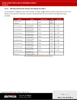
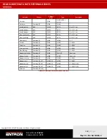
The iPAK2v2 control has 256 weld programs. As
shows, Parameters of weld program 0 through 255 are mapped
to addresses (Hexadecimal number)
16#0000
–
3FFF
. Each weld program (schedule) includes 64 words data. Weld
program 0 starts at address
16#0000
and ends at address
16#003F
, then each subsequent schedule uses the next 64
words addresses, with last schedule using address
16#3FC0-3FFF
. The address offset of each parameter in the weld
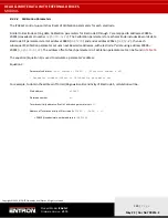
Based on the above description, the following equation (Equation 1
) is used to calculate a parameter’s address:
Equation 1:
Parameter’s address =
Start address (0000) + [Weld program number x 64] + Parameter
address offset in Weld program
For example, to obtain the address of Main current of weld program 5, calculation will be:
Start address
=
0000
Weld program number
=
5
Main current address offset in schedule =
12
Address of Main current of Weld program 5 =
0000 + [5x64] + 12
=
332 (Hexadecimal
number address is 16#014C)
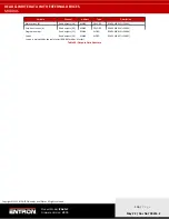
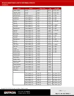
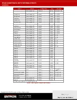
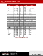
Variable
Channel
Address offset
Type
Description
Weld program
%IW0
WORD ARRAY [0..63]
Attributes
Weld program [0]
%IW0
WORD
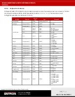
Pre heat
Bit 0
%IX0.0
BOOL
0 = off, 1 = on
Post heat
Bit 1
%IX0.1
BOOL
0 = off, 1 = on
Pre-mode
Bit 2
%IX0.2
BOOL
00 = PW mode
01 = CCu mode
10 = CCC mode
Bit 3
%IX0.3
BOOL
Main mode
Bit 4
%IX0.4
BOOL
00 = PW mode
01 = CCu mode
10 = CCC mode
Bit 5
%IX0.5
BOOL
Post-mode
Bit 6
%IX0.6
BOOL
00 = PW mode
01 = CCu mode
10 = CCC mode
Bit 7
%IX0.7
BOOL
Link mode
Bit 8
%IX1.0
BOOL
0 = off, 1 = on
Repeat / Roll-spot
mode
Bit 9
%IX1.1
BOOL
0 = off, 1 = on
Wait force
Bit 10
%IX1.2
BOOL
0 = off, 1 = on
Force profile
Bit 11
%IX1.3
BOOL
0 = off, 1 = on
Test force
Bit 12
%IX1.4
BOOL
0 = off, 1 = on


