


ADVANCED FEATURES
Electrode Management
169 |
P a g e
Copyright © 2021 BF ENTRON and/or its affiliates. All rights reserved
Product Model:
iPAK2v2
Firmware Version:
V2.10
May 22 | Doc No 700253-2
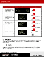
9.5.1.1
Stepper Outputs
For MODBUS and Ethernet/IP communications, the stepper status information is output by the iPAK2v2.
Prewarn
–
the Prewarn output is active when the stepper function is 90% complete and on the last step.
Stepper
–
The End Stepper output is active at the end of the last step.
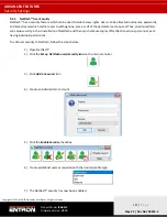
9.5.1.2
Preset Values
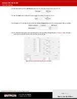
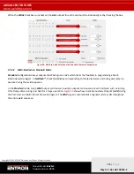
To expedite programming, the NetFlash™ software has preset values to populate the stepper table with initial values.
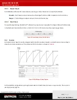
In the Electrode Tab on NetFlash, Click on the P1, P2, P3, P4 or P5 icons to load the preset stepper tables.
Figure 45: Preset Stepper Curve Action Buttons
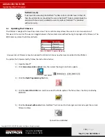
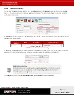
9.5.2
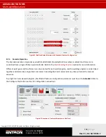
Counters
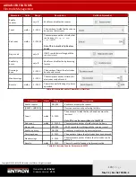
Each electrode can have the counter programmed to track the number of welds on an electrode and create stops to
allow for electrode maintenance. The parameters for the Counter are shown in
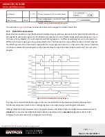
Figure 46: Weld Stepper Timing Diagram
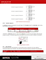
For Multi-Welder configurations, up to eight electrodes and transformers can have a unique counter. The counter is
used by all weld programs.