


7
Before starting, all electric and hydraulic connections must be
made. High pressure hoses, maximum pressure 10,000 psi (700
bar), are used to connect the cylinders with the oil ports of the
pump. When using double-acting cylinders it is important that
extension and retracting side are not confused. When coupling,
care should be taken to avoid any dirt getting into the system. To
allow unrestricted oil flow, all couplers have to be tightened firmly
by hand. No tools are necessary for connecting the couplers.
WARNING:
Never install any additional software to
the PC, cause this might damage or influence the
synchronous lift software. ENERPAC does not take
any liability for damage or accidental operation of the
synchronous lift system, if the synchronous lift file if affected
by any other software.
IMPORTANT:
Quick couplers should be used on the
hose assemblies, manifold and valves, to facilitate
system assembly and disassembly. All fittings must
be free of dirt or other contaminants when assembled.
Contaminants in the hydraulic oil could cause damage to
sensitive hydraulic components.
CAUTION:
We recommend to calculate the working
pressure of any individual cylinder before starting the
lifting job. The first step should be a test-pressurizing
of any cylinder (cylinder by cylinder) with a certain overload
(110 - 125% of calculated load) to ensure that the surface the
cylinders are placed on will be able to take the load. This can
easily be done using the mode "automatic (load)". After
starting the lifting process, check all circuits for the right
pressure (load).
IMPORTANT:
Cycle the cylinders up and down several
times to work the air out of the system. Once the air is
out of the system, check the cylinder foundation to
insure a firm steady reaction surface. Advance each cylinder
one at a time to maximum pressure, without lifting the load.
Check the foundation for cracks, cylinder sinking, or uneven
reaction surface.
7.0 HYDRAULIC COMPONENT ASSEMBLY
(Refer to Figures 1 and 2)
CAUTION:
It is very important to ensure the hydraulic
system remains free of contaminants. Make sure that
all hydraulic couplers and fittings are free of dirt
before assembly. A quality thread sealant such as Teflon tape
should be used to seal the threads on the hydraulic fitting. Use
1.5 wraps of Teflon tape leaving the first complete thread free
of tape to prevent tape from entering the hydraulic system.
The use of inline filters such as the Enerpac FL-2102 filter can
be installed at the outlet ports of the valve manifold. These
filters have a replaceable filter element and are effective in
protecting the system components when the contamination
level is suspect. Contaminants in the hydraulic system may
cause poor system performance and/or system failure.
A.
Install an Enerpac V-66F or a V-8F, if lifting less than 100 tons
of total weight, at the advance port of the VSP-424 valve,
stamped "A" or the pump mounted or remote directional
control valve. The port marked "CYL" on the body connects to
the advance port.
B.
Install pilot operated SCK-1 CHECK VALVE PACKAGES on
each lifting cylinder. The port marked "CYL" on the check
valve body connects to the advance port of the cylinder using
the fitting provided. The quick coupler in the cylinder advance
port is removed and used in the "pump" port of the check
valve body (
NOTE:
This coupler must be an Enerpac CR-400
or equivalent). Install the "tee" provided between the cylinder
retract port and the coupler. Install the pilot line between the
"tee" of the retract port and the port marked "RET/PILOT" on
the check valve body. The pilot line can be tubing or hose.
C.
Hydraulic tube or hydraulic hose capable of withstanding
10,000 psi (700 bar) system pressure.
D.
Place a hydraulic lifting cylinder at each lift point. Do not place
the cylinder under the lift point until all the electrical
components have been connected, and the control of each
cylinder has been verified as outlined in the CYLINDER
CONTROL CHECK section 10.4.
E.
Identify each lifting point with a number (1 through 8 for an
eight point lifting system). Lift point identification is necessary
to ensure correct matching of hydraulic lifting components
with electronic components.
F.
Plumb the remaining components of the hydraulic system as
follows:
• ADVANCE LINES
All cylinder advance lines are connected from a
common valve manifold which contains the individual
directional control valves (refer to Figures 1 and 2).
Keep track of which cylinder is attached to which port
on the manifold.
• RETRACT LINES
All cylinder retract lines are connected to a common
return manifold. The return manifold is then
connected to the retract port of the directional control
valve. In the case of an Enerpac VSP-424, this port is
labeled "B" and is the top port. Use a V-152, set at
1,800-2,000 psi (124-138 bar) on the retract port.
(Refer to Figures 1 and 2.)
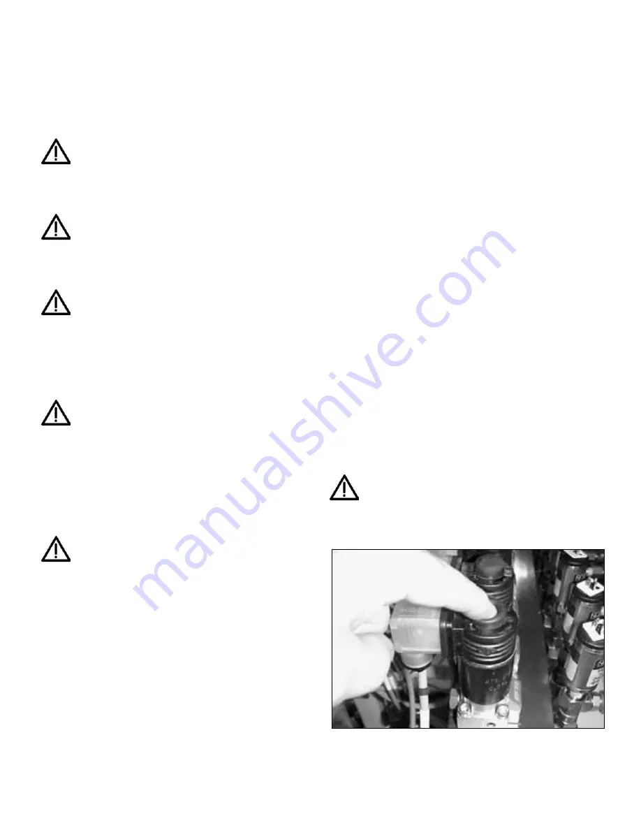
IMPORTANT:
The cylinder control valves have a
manual override capability. The valve is "normally
closed" and can be manually opened by depressing
the pin located in the center of the valve coil. The valve will
remain open when the pin is depressed and will return to the
closed position when the pin is released.
Figure 3
Содержание SLVS-8
Страница 99: ...99 L2543 O 08 01...
Страница 100: ...100...
Страница 101: ...101...
Страница 102: ...102...
Страница 103: ...103...
Страница 104: ...104...
Страница 105: ...105...
Страница 106: ...106 F E A C B D G...
Страница 107: ...107...
Страница 108: ...108...
Страница 109: ...109...
Страница 110: ...110...
Страница 111: ...111...
Страница 112: ...112...


