background image


3.3  Furnace Cabinet Installation – On an EL Tank 

Follow the directions in this section if you intend to mount the furnace to stands directly above 
the fuel tank. If you are mounting the furnace to a structural ceiling or wall proceed to Section 
3.4. 

Do not mount an EL-350H furnace to any EnergyLogic Tank smaller than 250 

gallons. 

3.3.1  Locate the EnergyLogic Used Oil Storage Tank 

EnergyLogic supplied workbench tanks are U.L. listed and pressure tested at the factory. 
However, new tanks must be leak tested by qualified installers prior to installation and use 
(refer to local codes and regulations). The tank must be located inside. If you are mounting the 
furnace to the tank, make sure that the tank is located beneath the desired location of the 
furnace. The tank must be on level flooring that will adequately support the full weight when 
loaded. Use a pallet jack or fork lift (on the bottom side of tank) to move the empty tank. Do not 
push or drag the tank. 


Maintain clearance from the tank to any source of heat 

(refer to local codes and regulations).


The furnace cabinet is heavy and will need to be lifted to a height of 8 feet 

above the floor. Use appropriate lifting and safety equipment.  

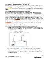
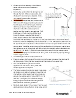
3.3.2  Tank Stands and Cabinet Installation (250 gallon tank shown) 

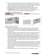
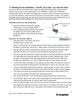
1.  Locate the two large “L-shaped” Support Stands, and slide the long end of each into 

the square tubes on the rear of the tank. Slide the stands all the way to the bottom and 
do not install any bolts at this time. 


2.  Inspect the furnace cabinet to make sure that the louvers for the heat output, the 

burner end, and the flue end are oriented as desired. If not, switch the louver panel on 
the front of the furnace with the blank panel that is on the rear of the furnace prior to 
installing the cabinet.  

Installation of support stands. 

Slide the L-shaped stands 
into the square tubes. 


12 

Call 1-615-471-5290 for Technical Support 

Содержание EL-140H

Страница 1: ...odels EL 140H EL 200H and EL 350H 115V 60Hz 5901 Crossings Boulevard Nashville TN 37013 www energylogic com 615 471 5290 Installation Operation Manual Designed to save Built to last Item 98030028 Issue Date 28 April 2015 ...

Страница 2: ......

Страница 3: ...allation practice shall be made according to CSA standard B139 Installation Code for Oil Burning Equipment Product improvements are occurring regularly so the products may vary slightly from what is shown in this manual If you have any questions or concerns during the installation or operation of the furnace contact your local service representative or EnergyLogic Thank you for purchasing an Energ...

Страница 4: ...allation On an EL Tank 12 3 3 1 Locate the EnergyLogic Used Oil Storage Tank 12 3 3 2 Tank Stands and Cabinet Installation 250 gallon tank shown 12 3 4 Furnace Cabinet Installation Not Mounted on a Tank 14 3 4 1 Ceiling Mount with Threaded Rod 14 3 4 2 Wall Mount with Optional Brackets 15 3 5 Preparing the EnergyLogic Used Oil Tank 16 3 5 1 Tank Vent Installation EnergyLogic Tanks 16 3 5 2 Drain V...

Страница 5: ...e Installation included with some packages 29 6 Electrical System Installation 30 6 1 Wall Thermostat 30 6 2 Fuel Pump Power Connection 32 6 3 Main Electrical Connection 33 7 Startup and Operation 34 7 1 Do s and Don ts Tech Tips 34 7 2 Burner Primary Control Operation 34 7 3 Safety Systems and Warnings 35 7 4 Furnace Startup 36 7 4 1 Fuel System Priming 36 7 4 2 Starting the Furnace 38 7 4 3 Burn...

Страница 6: ...es 69 9 3 1 Wall Thermostat Testing 69 9 3 2 Blower Assembly Testing 70 9 3 3 Cad Cell Testing 71 9 3 4 Metering Pump Assembly Testing 72 9 3 5 Preheater and Nozzle PTC Testing Procedure 74 9 3 6 Primary Control Testing 76 9 3 7 Solenoid Valve Testing 77 9 3 8 Top Suction Kit Testing 78 9 3 9 Iron Core Transformer Testing 79 9 3 10 Fan and Limit Controller Testing 81 10 Appendices 82 10 1 Furnace ...

Страница 7: ...afety this manual uses the following definitions and signal words to identify hazards Danger Indicates an imminently hazardous situation which if not avoided will result in death or serious injury This signal word is limited to the most extreme situations Warning Indicates a potentially hazardous situation which if not avoided could result in death or serious injury Caution Indicates a potentially...

Страница 8: ...is off for extended periods The furnace is designed to be installed above head height or in a manner that restricts access USED OILS CONTAIN HEAVY METALLIC COMPOUNDS AND FOREIGN MATERIALS WHEN BURNED THESE COMPOUNDS ARE EMITTED FROM OR DEPOSITED WITHIN THIS HEATING APPLIANCE AND THEREFORE CARE SHOULD BE TAKEN WHEN USING CLEANING AND MAINTAINING THIS EQUIPMENT EnergyLogic recommends that the buildi...

Страница 9: ...r heat exchanger and flue pipe on a scheduled basis Follow the minimum maintenance instructed in section 8 Wear proper protective clothing including gloves and face mask or respirator whenever any cleaning is performed including the cleaning of the heat exchanger flue piping and exhaust stack Vapor Dust Ignition Do not store or use gasoline or other flammable liquids or vapors near this furnace as...

Страница 10: ...ith all the regulation authorities having jurisdiction as well as CSA Standard B 139 Installation Code for Oil Burning Equipment Electrical installation in Canada shall be in accordance with the Canadian Electrical Code Part I CSA standards are available at www csa ca A qualified installer is an individual or agency who is responsible for the installation and adjustment of the equipment and who is...

Страница 11: ...nclude but are not limited to Gasoline Hazardous Waste Anti freeze Carburetor Cleaner Paint Thinner Any Chlorinated Material Parts Washer Solvents Oil Additives Animal Fats The addition of inappropriate substances to the fuel is not approved and can lead to poor equipment performance premature product failure and or explosive hazardous conditions Burning of fuels that contain unapproved substances...

Страница 12: ...t 24 Sides 6 Rear 6 Flue Pipe Single Wall 18 Bottom 6 Warm air duct within 3 of furnace when ducted 6 18 46 cm from outer surface of single wall flue tee pipe in all directions 6 15 24 cm from blower edge 24 61 cm from front of cabinet 6 15 24 cm from rear of cabinet 24 if using rear air panel discharge 6 15 24 cm from burner 72 183 cm recommended for maintenance access Warm air duct minimum clear...

Страница 13: ... not installing the pump to an EnergyLogic Tank mount it according to guidelines in the EnergyLogic Top Suction Kit packaging instructions 9 Do not kink copper tubing Route tubing as straight and vertical as possible no loops to avoid air pockets 10 Remember to remove the blower shipping strap prior to installation 11 Maximize vertical run of flue and minimize horizontal run Allow access for clean...

Страница 14: ... copper conductors only Electricity is very dangerous Wiring must be installed by a qualified electrician In the U S consult the National Electric Code NEC and local building codes for additional requirements In Canada consult the Canadian Electrical Code Part I Flue Pipe Is ceiling roof or wall location suitable for a flue pipe to pass through Are any obstacles or flammable materials present at i...

Страница 15: ...e oil tank Cabinet Orientation vs Air Flow Direction Consider the workspace to be heated Consider proximity to windows doors etc The EnergyLogic used oil furnace is designed such that the louver and cabinet panels may be swapped and the cabinet can be rotated 180º Consider whether or not this would be advantageous for your application Contact EnergyLogic if louvers are needed on both sides Structu...

Страница 16: ...any parts were damaged during shipment please contact your shipping carrier 3 2 Warranty Registration IMPORTANT You must register your furnace with EnergyLogic for the warranty to become active and to receive technical service Please take a few minutes to fill out the Warranty Registration Card Note Your Warranty Registration Card may be found in the accessory box where you located this manual You...

Страница 17: ...18 EnergyLogic Workbench Tank 1 19 Drain Valve Assembly 1 20 Swing Arm Fuel Gauge 1 21 3 8 Copper Discharge Line with Flare Nuts 1 22 L Shaped Tank Stands 2 23 Tank Stand Plastic Caps 2 24 Support Braces plus hardware EL 350 only 2 25 Cable Ties 2 26 Bolts 3 8 x 4 to mount stands 4 27 3 8 Flat Washers 8 28 3 8 Lock Washers 4 29 3 8 Nuts 4 30 Low Fuel Cut Off Switch Assembly 1 31 FireStop Valve Ass...

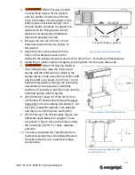
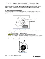
Страница 18: ...hen loaded Use a pallet jack or fork lift on the bottom side of tank to move the empty tank Do not push or drag the tank Maintain clearance from the tank to any source of heat refer to local codes and regulations The furnace cabinet is heavy and will need to be lifted to a height of 8 feet above the floor Use appropriate lifting and safety equipment 3 3 2 Tank Stands and Cabinet Installation 250 g...

Страница 19: ...tubing on the rear of the tank EL 140H and EL 200H only Insert 4 3 8 inch x 4 inch bolts with flat washers through the box tubing and stands 2 sets per side Install flat washers lock washers and then nuts onto the bolts and tighten refer to figure 8 EL 350H only Insert 2 of the 3 8 inch x 4 inch bolts with flat washers through the lower holes only on the box tubing and stands 1 set per side Instal...

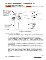
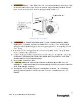
Страница 20: ...end of the rods furnace end 3 Turn nuts onto the this end of each threaded rod keep turning until the nuts are several inches up the rod 4 Using proper lift equipment carefully lift the furnace cabinet to the desired location Remove the existing 3 8 bolts from the top of the cabinet Place a lock washer and flat washer on each rod while you screw the threaded rod 1 2 54 cm into the threaded holes i...

Страница 21: ... to order your parts 2 Hang the EnergyLogic Wall Mount Brackets such that they are spaced 40 inches 101 6 cm apart to match the hole pattern on the bottom or top of the cabinet Hang the EnergyLogic Wall Mount Brackets directly to structural wall support only If the wall does not have structural support in the location of the brackets you may bridge across structural wall members using structural s...

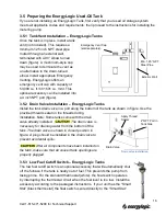
Страница 22: ...d sealer on the threads during installation Note Some tanks come with the drain valve already installed The drain valve is necessary for draining water from the bottom of the tank The drain valve is shown in closed position in figure A plug should be installed in the drain valve to prevent accidental spills After all components have been installed on the tank make sure that all unused tank opening...

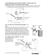
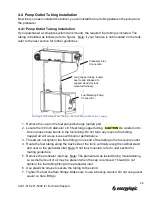
Страница 23: ...T fitting and screw the fire stop valve to the fuel filter head fully tighten the NPT threads using a back up wrench Then apply sealer to the NPT fitting and screw the entire filter head assembly with firestop valve into the NPT port in the side of the tank located about 10 up from the floor 3 6 2 Metering Pump Installation EL Tank Mount the pump to the integrated bracket on the EnergyLogic tank u...

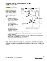
Страница 24: ...ithout kinking into position as shown 4 Thread do not tighten upper 3 8 inch flare nut onto the flare fitting on the fuel pump inlet Do not apply gasket sealer to the flare fittings 5 Thread lower fitting onto the filter head fitting 6 Tighten both flare nuts Use a backup wrench do not over tighten NOTE If your unit is equipped with a Smart Stat black thermostat there is an additional tee and vacu...

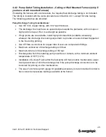
Страница 25: ...ecommended fuel temperature is 50o F The pump may be mounted to a nearby wall within a few feet less than 6 of the tank The ideal placement of pump is with the inlet above the filter head assembly which should be mounted above the tank fitting Maximum vertical lift for the suction line should not exceed 6 feet 2m This includes the portion of line inside of the tank The EL Filter Head Assembly is t...

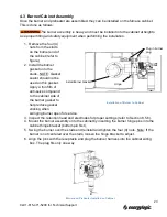
Страница 26: ... side of the blower with the shipping strap or cardboard support and remove the wire guard if installed on that side 2 Remove the shipping strap or cardboard support 3 Spin the blower wheel by hand to ensure that it spins freely 4 Align the three loops in the wire guard over the holes in the blower side panel For 140 and 200 model blowers insert a rubber washer under each loop Attached the wire gu...

Страница 27: ...e and white wires from the conduit to the two blower motor wires in the junction box using wire nuts Either color cabinet lead can go to either motor lead blower motor will run correctly either way 9 Reinstall the junction box cover 10 Make sure that the blower harness conduit located on the top of the cabinet is at least 2 inches away from the exhaust pipe or damper tee as the heat from these cou...

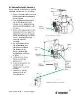
Страница 28: ... tested during manufacturing so a small amount of oil may be present when the caps are removed 4 Cut the tie strap holding the curled tubing and thread do not tighten the fittings onto the burner solenoid valve and preheater as shown in figure 5 Tighten the fuel tubing fittings and the long preheater bolt 6 Screw the plug end of the conduit into the receptacle on the burner wire box 7 Install the ...

Страница 29: ...burner gasket to help reduce gasket sticking when swinging burner open for service 3 Inspect the retention head and electrodes for proper settings refer to Section 8 5 6 4 Mount the burner assembly onto the cabinet by inserting the burner hinge pins into the cabinet hinge bracket bottom pin first 5 Swing the burner over the studs and reinstall and tighten the four 4 nuts Note If the burner is not ...

Страница 30: ...n the flare fitting on one end of the tubing to the fuel pump outlet 4 Route the fuel tubing along the back side of the tank vertically along the cabinet stand and over to the preheater inlet Note If not tank mounted refer to next section for routing guidelines 5 Remove the preheater inlet cap Note The preheater was tested during manufacturing so a small amount of oil may be present when the cap i...

Страница 31: ... available accessory wherever the discharge line routing steps down to provide a means to bleed trapped air in the line during priming Use 45 flare connections for copper tube Never use compression fittings Maximum vertical run of discharge tubing is 30 feet Maximum total run of discharge tubing is 150 feet Discharge line from the metering pump must be run indoors with a minimum ambient temperatur...

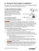
Страница 32: ...n consult NFPA 31 and your local fire protection and building codes Flue System Installation Steps and Considerations Review this section completely Choose and purchase a factory built flue kit that complies with U L standard 103 Type HT or Equivalent The EL 350H requires an 8 inch diameter flue and may not be reduced The flue connector for EL 140H and EL 200H may only be reduced down to 6 inch di...

Страница 33: ...ith national safety standards such as NFPA 31 54 and 211 Refer to fire and building codes for further requirements Improper installation of the flue system could result in property damage serious injury or death Avoid 90 degree elbows and horizontal runs Properly support the flue stack Do not rely on the furnace to support the total load of the flue system Follow the flue manufacturer s instructio...

Страница 34: ...rom smoke inhalation and or fire Use of exhaust fans in your shop without adequate make up air may create a negative pressure There are other possible causes as well Corrective measures must be taken before operating the appliance if the correct draft setting cannot be achieved Contact EnergyLogic or consult a local professional for assistance Damper Tee Installation Installation of vertical stack...

Страница 35: ...d with the gauge separate the tubes as only one is needed Attach the one end of a tube to the draft gauge port labeled Low at top of the gauge Note By doing this the negative readings will now read positive on the gauge scale This is to take advantage of the larger scale on the positive side 6 Locate the draft gauge probe which is a piece of stainless steel tubing with a U bend in it Thread a 1 4 ...

Страница 36: ...at will be mounted 5 Drill holes and install wall anchors provided 6 Pass the wire harness through the large opening found at center of the wall plate 7 Mount the wall plate to the wall by threading the provided screws into the wall anchors 8 Connect the black thermostat wire to the R Terminal 24V AC power by loosening screw in R Terminal inserting wire and tightening screw NOTE If installing an E...

Страница 37: ...4 Route the thermostat wire to the burner and connect the plug on the burner end of the cable to the receptacle at burner wiring box refer to figure Thermostat Wiring with Low Fuel Cutoff Switch Thermostat Wiring without Low Fuel Cutoff Switch 31 Call 1 615 471 5290 for Technical Support ...

Страница 38: ...ound wire to the ground screw on the middle housing bracket 4 Reinstall fuel pump housing cover 5 NOTE If making your own harness Remove cabinet wire box cover On the cabinet wire box terminal block connect the orange wire to the terminal marked ORG the white wire to the terminal marked WHT and the green ground wire to the terminal marked GND Insert stripped ends of wires into the terminal holes G...

Страница 39: ...C size 12 AWG Route the conduit from the cabinet wire box to the installed junction box Connect the conduit to wire box knock outs on box 3 Using wire nuts connect the black wire Load from the conduit to the black wire of the junction box the white wire Neutral to the white wire and the green wire Ground to the bare copper wire inside the junction box Install the junction box cover 4 Note If makin...

Страница 40: ...ers 11 PERFORM THE RECOMMENDED PERIODIC MAINTENANCE 12 Unplug the burner during the off season summer to prevent coking of the preheater and nozzle 7 2 Burner Primary Control Operation The burner operation is governed by the Primary Control shown in figure on next page This device is pre programmed and is not adjustable The important interface points are as follows The two T Terminals are for the ...

Страница 41: ...om is warm and the thermostat opens 7 3 Safety Systems and Warnings Several systems built into the burner controls ensure that the burner operates safely and will shutdown if something is wrong Preheater Thermostat This device prevents the primary control from attempting to start the burner with fuel that is too cold below 120o F In addition if the oil temperature drops below the limit while the b...

Страница 42: ... and amber LED lights on If lockout mode occurs do not continue to try to operate the burner until the problem has been resolved Call for service To reset the control from lockout press and hold the reset button down for one minute Note that controller models vary 7 4 Furnace Startup Prior to the initial startup of the furnace it is important to make sure the fuel system is properly primed to remo...

Страница 43: ...inted away from the burner Then re tighten the fitting at the preheater outlet to seal during priming 8 Place a container under the open end of the fuel tubing 9 Jump one set of alligator clips across the T T terminals red wires on the primary control to simulate the thermostat requesting heat The primary control delays the start for 3 seconds 10 Once the burner motor starts immediately jumper acr...

Страница 44: ... DO NOT ATTEMPT TO START THE BURNER WHEN EXCESS OIL HAS ACCUMULATED WHEN THE FURNACE IS FULL OF VAPOR OR WHEN THE COMBUSTION CHAMBER IS VERY HOT Refer to section 8 5 1 heat exchanger cleaning for instructions on removal of excess oil DO NOT START THE BURNER UNLESS ALL CLEANOUT PANELS ARE SECURE IN PLACE 1 Verify the Red LED on certain models on the primary control is not on or flashing You may nee...

Страница 45: ...ustment weight on the barometric damper door then slide it to the right or closer to the damper door pivot axis and retighten it If the draft gauge reading is more than 0 05 in WC Slide the weight to the left or away from the damper door pivot axis and retighten it Verify that the reading remains at 0 05 inches of WC with exhaust fans and vented appliances on in your building and all doors and win...

Страница 46: ...cuum reading is reading above normal check the following o Inlet to the suction line is clear of obstructions and all valves including fire stop valve are open o Fuel filter must be clean was it clogged with sludge from the tank o Oil must be above 50 F 10 C o Review how the pump is mounted compared to the instructions Burn Quality Visual Check When the burner is operating properly the flame is br...

Страница 47: ... Closed Air Band EL 350H 4 for Plate 4 for Air Band Burn Quality Smoke Measurement A qualified service technician may measure smoke content following procedures of his smoke pump Acceptable results per smoke pump comparison chart zero or 1 smoke spot A yellow brown smoke spot color is normal when burning used oil due to the presence of non combustibles The absence of black or dark grey soot indica...

Страница 48: ...e furnace at low fuel levels When filling the tank be careful not to agitate the oil so that air sludge are not introduced into the fuel pump Pre screen the oil prior to putting it into the tank Occasionally have your tank drained and cleaned Monitor the System After your initial set up monitor the system gauge readings on a regular schedule to assure that the system is stable Record the readings ...

Страница 49: ...e cleaning tool are the best tools to use with the maintenance procedures Clean preheater and replace gaskets annually Clean inspect solenoid valve and replace o ring annually Clean inspect nozzle and flame retention head and replace nozzle or o ring annually Compressor maintenance annually Ash removal every 800 1000 hrs Clean Blower Wheel every 800 1000 hrs Ash removal every 800 1000 hrs Drain wa...

Страница 50: ...mends that you monitor and record your system gauge readings regularly over time in order to diagnose issues that may arise For example if the pump vacuum gauge initially read 2 inches Hg but over time has risen to 10 inches Hg it is an indication that the fuel filter is most likely clogged up Record the system gauge readings on your maintenance schedule and log Have this log handy if you call Ene...

Страница 51: ...45 Call 1 615 471 5290 for Technical Support ...

Страница 52: ...s flue brush accessories Personally verify that the main power is turned off and locked out at the circuit breaker Main Heat Exchanger Cleaning 140H and EL 200H Procedure for Heat Exchanger Cleaning EL 140H and 200H 1 If furnace is hot allow it to cool before cleaning Wear all safety equipment 2 Unplug the burner at the cabinet wiring box 3 Close the hand valve on the bottom of the preheater 4 Dis...

Страница 53: ...w holes and replace screws 16 Inspect Burner Gasket If damaged replace the gasket PN 20910103 17 Swing the burner over the four studs to close and reinstall the nuts 18 Reinstall the fuel tubing on the preheater and open the hand valve 19 Make sure to perform start up 7 4 2 and system checks 7 4 3 after every maintenance cycle Record the checks maintenance performed and gauge readings in the maint...

Страница 54: ...5 Reattach the trash bag then reach through the bag grab the brush and clean the ash from the flue pipe by running it up through the flue pipe Clean all flue pipe from other access points if extension rods do not reach from the bottom of the furnace 16 Remove the trash bag brush and properly dispose of the ash 17 Inspect the cleaned heat exchanger and flue If damaged replace damaged parts 18 Inspe...

Страница 55: ...Blower and Internal Baffle Can Be Removed for Access to Clean the Flue from the Bottom 350H 49 Call 1 615 471 5290 for Technical Support ...

Страница 56: ...nd locked out at the circuit breaker Procedure All Models 1 Wear all safety equipment 2 Remove wire guard from the Blower Wheel side refer to figure 3 Using a small pipe brush and shop vacuum gently clean dust from the Blower Wheel Blades Be careful not to damage the blades 4 When finished reattach the wire guard Blower Cleaning Remove screws and wire guard Gently clean the blower wheel 50 Call 1 ...

Страница 57: ...ilter wrench to spin the Fuel Filter off the Filter Head Assembly counter clockwise Dispose of the fuel filter properly 4 Clean any debris from the strainer housing 5 You may fill new Fuel Filter with non synthetic ATF to quicken the priming process Do not use new motor oil or synthetic ATF to fill the filter 6 Spin the Fuel Filter onto the Strainer Housing clockwise Hand tighten the filter Record...

Страница 58: ...quipment 2 Unplug the burner at the cabinet wiring box 3 Disconnect the Preheater Connector at the Burner Wiring Box allow it to cool Until the preheater has cooled the parts and the oil are hot 4 Close the preheater inlet valve and disconnect the fuel tubing from the Inlet and Outlet Ports of the Preheater 5 Remove the Preheater mounting bolt and Preheater from the burner Unplug burner Preheater ...

Страница 59: ...housing and Top Cap with parts washer fluid 11 Unscrew the Bottom Cap inlet from the housing 12 Remove the old gasket from the cap 13 Clean the cap and valve then replace the gasket 14 Reinstall the Bottom Cap onto the housing 15 Replace the Top Cap gasket by carefully sliding it over the extrusion 16 Reinstall the Extrusion Top Cap onto the housing Do not over tighten 17 Remount the Preheater ont...

Страница 60: ...rify that the main power is turned off and locked out at the circuit breaker Procedure All Models Refer to figures 1 Wear all safety equipment 2 Remove the preheater and burner from the furnace refer to previous sections 3 Using a 7 16 wrench disconnect the fuel and air tubing from the Nozzle Block 4 Using a 17mm boxed end 12 pt wrench remove the knurled nuts from the Nozzle Block refer to figure ...

Страница 61: ...he collar set screw 11 Slide the Air Vane off the Nozzle Line Assembly 12 Using a 5 8 in socket ratchet remove the Nozzle from the Nozzle Block Assembly Slide nozzle assembly out of burner assembly Removing Nozzle Block Inspect Electrodes for Wear Disassemble Nozzle Block Set Screw Retention Head Nozzle Block Assembly Air Vane Electrode Assembly Nozzle 2 Pin Connector Nozzle Block Assembly New Ele...

Страница 62: ...ORTANT Being careful not to apply parts washer fluid to the heater wiring harness clean the nozzle passage of the Nozzle Block Make sure parts are clean and dry prior to reassembly 20 Refer to the following section 8 5 6 for Flame Retention Head and Electrode Settings and reassemble the Nozzle Line Assembly Be sure to re install the air vane shown in figure in the proper location opposite side of ...

Страница 63: ...must be 1 16 1 6 mm behind the Cap of the Nozzle Nozzle protrudes approximately 1 8 3 mm beyond Retention Head vanes Vertical location of electrode wires 7 16 1 6 mm from center nozzle to wires Make sure that there is a gap between the electrode wires and the nozzle Make sure there is a gap between the retention head inner diameter and the electrode wires NOTE For the Single Bend electrode the sam...

Страница 64: ... by the retention head base For the Double Bend electrodes the retention head should be installed with one leg vertical and the electrodes straddle that leg For the Single Bend electrodes the extra cutout in the center hole of the retention head should be centered vertically and the electrodes are mounted in that cutout between two legs A tab on the collar of the retention head fits into the chann...

Страница 65: ... 16 inch wrench remove the two fuel tubing fittings from the Solenoid Valve refer to figure 3 Loosen the fittings at the other end of the fuel tubing at the preheater and burner nozzle block then rotate the tubing out of the way refer to figure 4 Remove the E Clip from the top of the solenoid Slide the solenoid body and stem from the bottom of the housing you may need to rotate the housing 5 Using...

Страница 66: ... small pick making sure not to damage any surfaces 11 Reassemble the Solenoid Valve in reverse order of disassembly Make sure the arrow is pointing in the correct direction of flow 12 Make sure to perform start up 7 4 2 and system checks 7 4 3 after every maintenance cycle Record the checks maintenance performed and gauge readings in the maintenance log Remove E Clip Slide Valve out Body O Ring Nu...

Страница 67: ...tubing 4 Start the burner by moving the wall thermostat above room temperature and note the air compressor output on the gauge If the gauge reading is in the 9 11 PSI range the air compressor is operating as designed and no further maintenance is required Remove the test kit and reinstall the 3 16 tubing for normal operation 5 If the gauge reading is below 9 PSI check do the following A Coupling 1...

Страница 68: ... replacement kit PN 10013106 5 Reassemble the air compressor Be careful not to over tighten the cover plate C Cleaning Wear Safety Glasses 1 Disconnect the fitting at the air compressor outlet 2 Disconnect the preheater outlet tubing from the solenoid valve and run into a bucket to catch the oil 3 Jump the primary control T terminals then F terminals to operate the burner 4 Feed several drops of t...

Страница 69: ...ater valve and drain the oil from the preheater 5 Perform annual maintenance Refer to maintenance log Start Up Procedure 1 Inspect the flue wind cap for obstructions such as bird nests or leaves 2 Perform annual maintenance tasks if not yet completed Refer to maintenance log 3 Make sure that the used oil storage tank has enough oil 4 Turn power on to the furnace at the breaker or plug the burner i...

Страница 70: ...ade to the building or structure Common things to verify are a Is the fuel in the tank low Has it run dry and the pump lost prime b Fuel Pump and Filter Installation Dirty Filter c Fuel condition changed bad fuel water in fuel d Adequate combustion and make up air Have exhaust fans or other devices been added to the building that may create a negative pressure within the building Has another fuel ...

Страница 71: ...tion 9 2 7 Fuel Quality See Section 9 2 05 Smoke is seen from the external flue cap or internal damper door or the furnace is running rough 1 Go to Behavior Tree 4 1 Pump Filter See Section 9 2 2 Go to Tree 2 See Section 9 2 1 Wall T Stat See Section 9 3 2 Blower Fan Limit See Section 9 3 3 Primary Controller See Section 9 3 1 Heat Exchanger See Section 9 2 2 Damper Tee Manometer See Section 9 2 3...

Страница 72: ...Yes Go to Next Component No Verify operational status by following the steps in the Air Compressor Maintenance in Section 8 5 8 starting with section B of the Procedure If okay replace burner motor Burner Plug 1 Check the connections underneath the burner plug casing male end Are the connections tight and free of damage Yes Go to Next Action Question No Repair connections Damper Tee Manometer 1 Ve...

Страница 73: ...on of the primary control What is the fuel pressure reading gauge at pump outlet PSI while burner is running 0 or erratically fluctuating then Go to Action Question 4 or greater than 20 psi see Nozzle Solenoid cleaning or between 3 and 15 normal go to Component 3 Fuel line check Do the fuel lines contact an exterior cold wall Yes If fuel line is in contact with an exterior wall this could result i...

Страница 74: ...h copper line that leaves the fire stop valve at the tank Yes Repair Replace leaking component s No Go to Next Component Tank Tank Controls 1 In the tank from which the metering pump is supplied is the fuel pickup submerged into the oil source Yes Go to Next Action Question No Fill Tank 2 Is there continuity across the wires for the Low Level Cutoff Switch Yes Go to Next Action Question No Replace...

Страница 75: ...to order a new thermostat Procedure 1 Disconnect the Thermostat wires from the burner by removing the T Stat plug see image below and verify the pins on the plug and receptacle are straight and secure 2 If the system has a Fuel Low Cutoff Switch a Verify the fuel level in the tank is above the switch float If not then remedy b Check for continuity across the wires of the float switch If no continu...

Страница 76: ...hite button out 4 Remove blower wheel safety cage and verify the blower will freely spin and is clear of interference If a non correctable interference is present replace the blower assembly 5 Return cage to assembly and turn on the power at the supply breaker 6 Move the Fan Limit Control to Manual white button in and verify 120V at the blower wiring box If 0V check Fan Limit wiring connections 7 ...

Страница 77: ... receptacle 2 Loosen or remove two ignition transformer screws The cad cell is located on the underside of the ignition transformer Lift the ignition transformer and inspect the yellow cad cell leads for cuts or breaks 3 Inspect the cad cell for signs of overheating such as melted plastic or coating of soot Clean or replace if you see any of these signs 4 Gently wipe dust off the cad cell lens wit...

Страница 78: ...rminals 5 Use Caution when approaching the pump assembly rotating parts will be in operation 6 Chattering from the gear box usually means damaged gearing If chattering is heard or felt replace the gear box 7 Close the ball valve at the bottom of the preheater 8 Using a multi meter verify the voltage across the wires going to the pump motor should be around 115V AC a If voltage is not present check...

Страница 79: ... 15 Vacuum gauge reading should be the same as noted in step 14 a If not check fittings and connections and retest looking for signs of vacuum leaks Flow test 16 Disconnect the 3 16 copper line from the inlet of the solenoid valve at the top of the preheater you will use this tube to catch oil coming from the preheater 17 Have the graduated cylinder located so as to catch oil from the tube in step...

Страница 80: ...t high voltage electrical components will be energized Only a certified electrician is to perform the following procedures and with extreme caution Procedure 1 With the burner unplugged verify the pins at the preheater plug and receptacle are straight and secure 2 Check the 8 Amp fuse refer to figure below If the fuse is blown there is a high probability that at least one of the run PTCs has short...

Страница 81: ...plug refer to figure If the preheater is hot but there is no continuity across the thermostat pins the preheater will need to be replaced 7 If the burner does not light off well there may be a problem with the Nozzle Block Standby PTC To check the Nozzle Block Standby PTC Remove the screws and flip back the transformer on top of the burner to expose the nozzle block a Using the temperature probe o...

Страница 82: ...g to the F F terminals on the primary Testing the Limited Recycle Mode function of the Primary Control 3 Use the alligator clip or jumper wire to connect the T T terminals a Burner should run for several seconds resulting in reset b If this happens the primary control is working properly i If the burner does not operate unplug the burner and check the connections in the burner wiring box Then repe...

Страница 83: ...m terminal strip 4 Using a multi meter test for continuity across the solenoid wires There should be continuity across wires 5 Leaving the purple and white wires disconnected loosely replace the primary cover 6 Remove copper tubing from between the solenoid and the nozzle have cup or disposable towel ready to catch oil 7 Wear Safety Glasses for the following steps 8 Plug in the burner and jumper t...

Страница 84: ...ow fuel cut off function see Thermostat Testing Section 9 3 1 Procedure 1 Run the pump vacuum check Section 9 3 4 steps 12 16 and make sure that you have proper and tight flare connections If there is a leak repair it or call for assistance 2 Disconnect the 3 8 copper tube at union above the tank Disconnect wiring for low fuel cut off switch 3 Remove the suction copper and foot valve from tank 4 C...

Страница 85: ...he primary control 4 Find the Black wires coming from the transformer and cautiously check the voltage across the terminals Should read between 105 and 120 volts AC a If reading is not within range call your electrician to rectify voltage issue There may be an issue with your local power company 5 Remove jumpers from T T and F F terminals 6 Unplug the burner plug from its receptacle 7 Loosen or re...

Страница 86: ...i Using the amp clamp around the wire read the amperes 1 Reading should be between 20mA and 26mA with a nominal of 23mA transformer should be labeled 13 Remove jumpers from T T and F F terminals 14 Unplug the burner plug from its receptacle 15 Return the Transformer and Primary Controller to its operating position and plug in the burner 80 Call 1 615 471 5290 for Technical Support ...

Страница 87: ...furnace on and watch the fan and limit dial as the furnace rises in temperature The blower should come on when the Fan On temp is reached and stay on Turn the wall thermostat down to stop the burner The blower should stay on to cool the heat exchanger combustion chamber until it reaches the Fan Off temp on the dial 5 To check the high limit function turn power to the furnace off at the breaker box...

Страница 88: ...10 Appendices 10 1 Furnace Wiring and Oil Schematic 82 Call 1 615 471 5290 for Technical Support Furnace System Wiring Diagram ...

Страница 89: ... Control Circuit with 24 VAC thermostat Oil Schematic Wide Key at Top Standby Heater Neutral Standby Heater 115V Preheater Thermostat Run Heaters 115V Run Heaters Neutral Center Pin Not Used 83 Call 1 615 471 5290 for Technical Support ...

Страница 90: ...10 2 Carlin 50200E Primary Control 84 Call 1 615 471 5290 for Technical Support ...

Страница 91: ...85 Call 1 615 471 5290 for Technical Support ...

Страница 92: ...Size 25A Blower Motor 1 3 HP 115V 60Hz 6 1A 1 2 HP 115V 60Hz 8 1A 1 HP 115V 60Hz 11 8A Burner Motor 1 5 HP 115V 60Hz 3 3A 1 5 HP 115V 60Hz 3 3A 1 5 HP 115V 60Hz 3 3A Metering Pump Motor 15Watt 115V 60Hz 0 35A Ignition Transformer Control Circuit 115V 60Hz 2 0A Oil Preheaters 115V 60Hz 2 0A Maximum 115V 60Hz 2 5A Maximum 115V 60Hz 3 0A Maximum Minimum Clearance to Combustible Surfaces Top 6 Front 2...

Страница 93: ...87 Call 1 615 471 5290 for Technical Support ...

Страница 94: ...88 Call 1 615 471 5290 for Technical Support ...

Страница 95: ...89 Call 1 615 471 5290 for Technical Support ...

Страница 96: ...per handling storage or use in conjunction with other parts not authorized by MANUFACTURER 9 Products that have been moved from the original installation site or that have been sold or exchanged to a person other than the original buyer 10 Equipment or products installed outside of the continental U S or Canada 11 Products or parts in which the serial number has been altered defaced or removed The...

Отзывы: