


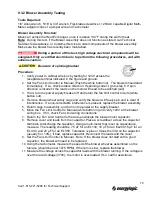

9.3.2 Blower Assembly Testing
Tools Required:
1/8” Allen wrench, 5/16” & 3/4” wrench, Flat-blade screwdriver, 120VAC capable Digital Multi-
Meter, alligator clips or a jumper wire and Tachometer
Blower Assembly Function:
Moves air across the Heat Exchanger, once it is above 130°F during the call for heat.
Note:
During this test, if the Blower Assembly does not function as stated, call Technical
Services for assistance, or Customer Service to order components of the blower assembly.
Make sure the blower has recently been maintained.
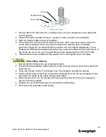
During a portion of this test, high voltage electrical components will be
energized. Only a certified electrician is to perform the following procedures, and with
extreme caution.
Be aware of spinning blades!
Procedure:
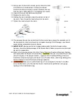
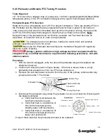
1.
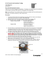
Verify power to cabinet wire box by testing for 120V across the
receptacle terminal indicated in the figure and ground.
2.
Set the Fan Limit Control to Manual (Push the white button in). The blower should start
immediately. If so, check rotation direction. If spinning correct, go to step 8. If spin
direction is incorrect, the leads on the motor will need to be switched (call).
3.
If not, turn the power supply breaker off and return the fan limit control to Auto (white
button out)
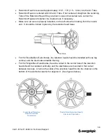
4.
Remove blower wheel safety cage and verify the blower will freely spin and is clear of
interference. If a non-correctable interference is present, replace the blower assembly.
5.
Return cage to assembly, and turn on the power at the supply breaker.
6.
Move the Fan Limit Control to Manual (white button in) and verify 120V at the blower
wiring box. If 0V, check Fan Limit wiring connections.
7.
Return the Fan Limit Control to the Auto and locate the blower motor capacitor.
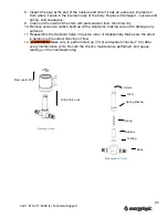
8.
Remove cover and leads from the capacitor. Place a screwdriver across the capacitor
terminals to discharge the capacitor. Using a multi-meter that is set on capacitance,
measure. The reading should be 7.5
μF for an EL140, 10 μF for an EL200,15 μF for an
EL 340, and 20
μF for an EL 350. Tolerance is plus or minus the limit on the capacitor
(usually 5 or 10%). If bad, replace capacitor. Reconnect the leads and the cover.
9.
Set the Fan Limit Control to Manual. Note: If the blower does not start with a good
capacitor, the blower will need to be replaced.
10.
Using the tachometer, measure the speed of the blower wheel as assembled on the
furnace (should be near 1075 RPM). If the rpm is slow, replace the blower.
11.
Measure the voltage across the capacitor leads with the blower running. If the voltage is
over the rated voltage (370V), the motor is over-loaded. If so, call for assistance.
70
Call 1-615-471-5290 for Technical Support
Содержание EL-140H
Страница 2: ......
Страница 51: ...45 Call 1 615 471 5290 for Technical Support ...
Страница 90: ...10 2 Carlin 50200E Primary Control 84 Call 1 615 471 5290 for Technical Support ...
Страница 91: ...85 Call 1 615 471 5290 for Technical Support ...
Страница 93: ...87 Call 1 615 471 5290 for Technical Support ...
Страница 94: ...88 Call 1 615 471 5290 for Technical Support ...
Страница 95: ...89 Call 1 615 471 5290 for Technical Support ...