background image

Operation

Levelflex M FMP43 with PROFIBUS PA

36

Hauser

5.3.2

Unlocking the configuration mode

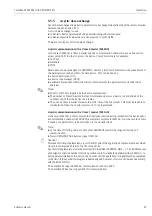
If an attempt is made to change parameters when the device is locked, the user is automatically 
requested to unlock the device:

"unlock parameter" (0A4):

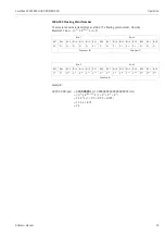
By entering the release code (on the display or via communication)

2457

 = for PROFIBUS PA devices

the Levelflex is released for operation.

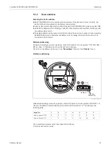
Hardware unlocking:

After pressing the 

O

 and 

S

 and 

F

 keys at the same time, the user is asked to enter the release code

2457

 = for PROFIBUS PA devices

"

Caution! 
Changing certain parameters such as all sensor characteristics, for example, influences numerous 
functions of the entire measuring system, particularly measuring accuracy. There is no need to 
change these parameters under normal circumstances and consequently, they are protected by a 
special code known only to the Hauser service organization. Please contact 
Hauser if you have any questions.

Press 

O

 and 

S

 and 

F

 simultaneously

Please enter release code and confirm with 

F

.

E HAUSER

E

+

Содержание Levelflex M FMP43

Страница 1: ...BA358F 00 en 07 07 No 71041163 Valid as of software version V 01 04 02 Operating Instructions Levelflex M FMP43 Guided Level Radar PROFIBUS PA 8...

Страница 2: ...f the display and operating elements can be found here Commissioning via VU331 display 55 In the Commissioning section you learn how to switch on the device and check the functions Commissioning via T...

Страница 3: ...ify range suggestion 000 measured value Group selection 00 basic setup 01 safety settings 09 display 04 linearisation 05 extended calibr 0C system parameters 092 language 0A diagnostics 0A0 present er...

Страница 4: ...Brief overview Levelflex M FMP43 with PROFIBUS PA 4 Endress Hauser...

Страница 5: ...aying and acknowledging error messages 38 5 5 PROFIBUS PA communication 40 6 Commissioning 55 6 1 Function check 55 6 2 Switching on the measuring device 55 6 3 Basic setup 56 6 4 Basic setup with dis...

Страница 6: ...ty supply commissioning operation and maintenance of the measuring system must only be carried out by trained qualified specialists authorized to perform such work by the facility s owner operator The...

Страница 7: ...the drawings of these Operating Instructions to indicate hazardous areas Devices in hazardous areas or cables for such devices must have appropriate explosion protection Safe area non hazardous area T...

Страница 8: ...ation according to Directive 94 9 EC and designation of protection Feature Option 10 Approval A Non hazardous area 1 ATEX II 1 2 G EEx ia IIC T6 7 ATEX II 1 2 G EEx d ia IIC T6 5 ATEX II 1 2 G EEx ia...

Страница 9: ...e ANSI B16 5 YY9 Special version to be specified 50 Power Supply Output B 2 wire 4 20 mA SIL HART D 2 wire PROFIBUS PA F 2 wire FOUNDATION Fieldbus G 4 wire 90 250 VAC 4 20 mA SIL HART H 4 wire 10 5 3...

Страница 10: ...version B EN 10204 3 1 material 316L wetted parts inspection certificate P CoC EN 10204 3 1 material 316L wetted parts inspection certificate Y Special version to be specified FMP43 Complete product...

Страница 11: ...d to meet state of the art safety requirements has been tested and left the factory in a condition in which it is safe to operate The device takes into account applicable standards and regulations whi...

Страница 12: ...ope of supply matches your order 3 1 2 Transport Caution Follow the safety instructions and transport conditions for devices of more than 18 kg Do not lift the measuring device by the probe rod in ord...

Страница 13: ...information dimensions and materials Dimensions for the process connection and the probe type 14 L00 F12xxxx 06 00 00 en 001 L00 T12xxxx 06 00 00 en 001 L00 F23xxxx 06 00 00 en 001 ENDRESS HAUSER 65 7...

Страница 14: ...urement Insulator Material Approval Ketron PEEK LSG FDA 3A USP Cl VI O ring see Feature 30 in Ordering information Material Approval Temperature range Option EPDM Freudenberg 70 EPDM 291 FDA 3A USP Cl...

Страница 15: ...2 DN25 38 1 to 1 Pmax 16 bar 0 8 m 0 38 m electropolished 5 certificate pending EHEDG tests passed certificate pending ASME BPE compliant TCJ Tri clamp ISO2852 DN40 51 2 Pmax 16 bar TDJ Tri clamp ISO2...

Страница 16: ...F50 Pmax 16 bar MRJ DIN11864 1 A DN25 Pipe DIN11850 with slotted nut F25 Pmax 16 bar 0 8 m 0 38 m electropolished MAJ NEUMO BioControl DN25 PN16 Pmax 16 bar S1J 1 1 2 150lbs RF Flange ANSI B16 5 Pmax...

Страница 17: ...on Endress Hauser 17 All metal parts used in the process in 316L 1 4435 Thread M24 x 1 5 Accessory weld in adapter U1J Weld in adapter order number 71041381 Pmax 16 bar 0 8 m Process connection Design...

Страница 18: ...y from the wall B that in the event of buildup on the wall there is still a minimum distance of 100 mm between the probe and the buildup Mount the probe as far away as possible from internals The mini...

Страница 19: ...he medium perpendicular to the probe rod d m Diameter of the probe rod 8 mm L m Level LN m Probe length L00 FMP43xxx 16 00 00 de 004 Calculation example L00 FMP43xxx 16 00 00 xx 003 Friction factor cw...

Страница 20: ...act process ultrasonic or level radar would be better suited particularly if the agitator generates large mechanical loads on the probe L00 FMP43xxx 17 00 00 xx 005 Installation at an angle For mechan...

Страница 21: ...ut L00 FMP43xxx 17 00 00 en 002 Note The cable cannot be disassembled at these points 1 The cable should never be bent or buckled The ambient temperature for the connecting line 2 between the probe an...

Страница 22: ...ixing screw 1 L00 FMP41Cxx 17 00 00 en 002 3 4 Post installation check After the measuring device has been installed perform the following checks Is the device damaged visual inspection Does the devic...

Страница 23: ...spray ball is used The cleaning jet is deflected against the tank wall and onto the probe This means that those parts of the probe are cleaned which would normally not be reached by the spray ball jet...

Страница 24: ...dapter o of the process connection The housing adapter is still connected with the housing At the remote version remove only the cable adapter Replace O ring where necessary Order number see 86 Disass...

Страница 25: ...e assembly is done in reversed order screw adapter o with 4 5 Nm on the probe rod p screw the adapter into the container process connection together with the probe rod and tighten with 20 Nm stick hou...

Страница 26: ...w It forms the connection between the antenna and the housing earth potential l l l 7 8 When you use the measuring system in hazardous areas make sure you comply with national standards and the specif...

Страница 27: ...specific cable gland Connect up the Levelflex M as follows Before unscrew housing cover 2 at seperate connection room turn off the power supply Insert cable 3 through gland 5 Use screened twisted wir...

Страница 28: ...er No 4 wire ENDRESS HAUSER t 85 C TA 70 C D01301 A if modification see sep label X Patents LEVELFLEX M 90 253 V AC 1VA 10 5 32 V DC 1W 16 3 V DC 0 8W Profibus PA Foundation Fieldbus LN PN 4 20 mA HAR...

Страница 29: ...h requires the use of an overvoltage protection according to DIN EN 60079 14 standard for testprocedures DIN IEC 60060 1 10 kA Puls 8 20 s it has to be ensured that the measuring device with integrate...

Страница 30: ...ations which are subject to the explosion prevention permit only under special conditions the repeated grounding of the protective screen see to EN 60 079 14 4 4 Degree of protection With closed housi...

Страница 31: ...hape 002 with or b confirms selection appears in front of the selected parameter c confirms the edited value system quits Edit mode d interrupts selection system quits Edit mode a Press or to edit the...

Страница 32: ...setup 00 function group include tank properties 002 medium property 003 process propert 004 empty calibr 005 etc If for example the application of the device is to be changed carry out the following 1...

Страница 33: ...ig 2 Display ENDRESS HAUSER E END RESS HAU SER MICR OPIL OT II END RESS HAU SER MICR OPIL OT II IP 65 IP 65 Order Code Ser No Order Code Ser No Messbe reich Measur ing range Messbe reich Measur ing ra...

Страница 34: ...e is locked i e if no entries are possible COM_SYMBOL This communication symbol appears when data are being transmitted e g via HART PROFIBUS PA or FOUNDATION Fieldbus Key s Meaning Oor V Navigate upw...

Страница 35: ...lock is indicated on the display by the symbol and can be released again either via the display or by communication Hardware locking The device is locked by pressing the O and S and F keys at the same...

Страница 36: ...e O and S and F keys at the same time the user is asked to enter the release code 2457 for PROFIBUS PA devices Caution Changing certain parameters such as all sensor characteristics for example influe...

Страница 37: ...eted The mapping can be deleted in the cust tank map 055 function of the extended calibr 05 function group A linearization is switched to linear but the table values are retained The table can be reac...

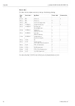
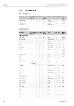
Страница 38: ...que error code is also output A description of the error codes is given on 82 The diagnostics 0A function group can display the current error as well as the last error that occurred If several errors...

Страница 39: ...ith the following operating systems WinNT4 0 Win2000 and WinXP The ToF Tool supports the following functions Online configuration of transmitters Signal analysis via envelope curve Loading and saving...

Страница 40: ...the segment coupler On site as well as remote operation are possible For detailed information on the PROFIBUS PA standard refer to Operation Instructions BA 198F 00 en and the standards EN 50 170 DIN...

Страница 41: ...8F 00 en chap 5 7 describes how to set the address in this case In ToF Tool the address can be set via the Set address function in the Device menu Hardware addressing L00 FMU4xxxx 19 00 00 en 014 Hard...

Страница 42: ...XXX 02 00 00 YY 001 The GSD files in the directory Extended are needed for the network design software STEP 7 of the S7 300 400 PLC family The GSD files in the directory Standard are used for PLCs whi...

Страница 43: ...068 determines whether at the display of the device in the field for the main measured value the measured value 000 or the value from the PLC display value 069 are displayed Modules for the cyclic da...

Страница 44: ...er to transmit the main value and the second cyclic value and to receive a display value select the modules in the following order Main Process Value 2nd Cyclic Value Display Value The exact way of pe...

Страница 45: ...1 Bit 0 Bit 7 Bit 6 Bit 5 Bit 4 Bit 3 Bit 2 Bit 1 Bit 0 VZ 27 26 25 24 23 22 21 20 2 1 2 2 2 3 2 4 2 5 2 6 2 7 Exponent E Mantisse F Byte 3 Byte 4 Bit 7 Bit 6 Bit 5 Bit 4 Bit 3 Bit 2 Bit 1 Bit 0 Bit...

Страница 46: ...1F Hex BAD out of service target mode X 40 Hex UNCERTAIN non specific simulation X 47 Hex UNCERTAIN last usable value Fail safe Mode aktiv X 4B Hex UNCERTAIN Substitute set fail Safe mode active X 4F...

Страница 47: ...r of SAPs that the device can provide The use of a Class 2 master increases the cycle time of the bus system This must be taken into consideration when the control system or PLC is programmed Acyclic...

Страница 48: ...2 UNSIGNED16 X X static Alert key 1 20 1 UNSIGNED8 X X static Target Mode 1 21 1 UNSIGNED8 X X static Mode 1 22 3 DS 37 X dynamic non vol constant Alarm summary 1 23 8 DS 42 X dynamic Batch 1 24 10 D...

Страница 49: ...y 0 23 8 DS 42 X dynamic Block parameters Software revision 0 24 16 OSTRING X constant Hardware revision 0 25 16 OSTRING X constant Device manufacturer ID 0 26 2 UNSIGNED16 X constant Device ID 0 27 1...

Страница 50: ...ontrol 0 57 1 UNSIGNED8 X dynamic Up Down param 0 58 20 OSTRING X X dynamic Bus address 0 59 1 UNSIGNED8 X dynamic Device SW No 0 60 2 UNSIGNED16 X dynamic set unit to bus 0 61 1 UNSIGNED8 X X static...

Страница 51: ...Full calibration V0H6 1 144 4 FLOAT x x static Tube diameter V0H7 1 145 4 FLOAT x x static Gap 146 147 Output on alarm V1H0 1 148 1 UNSIGNED8 x x static Gap 149 Outp echo loss V1H2 1 150 1 UNSIGNED8 x...

Страница 52: ...x static AI out value V5H3 1 191 4 FLOAT x dynamic AI out status V5H4 1 192 1 UNSIGNED8 x dynamic Simulation type V5H5 1 193 1 UNSIGNED8 x x static Simulation value V5H6 1 194 4 FLOAT x x static 2nd...

Страница 53: ...rescaled in two steps L00 FMUx3xxx 05 00 00 en 001 1 In a first step the main value is mapped to the interval 0 1 PV_SCALE_MIN and PV_SCALE_MAX determine the limits of this mapping Measured level V9H6...

Страница 54: ...nges the unit of the measuring value in the Transducer Block If units are changed PV_SCALE_MIN and PV_SCALE_MAX automatically adapt themselves in such a way that the output value remains unchanged Onl...

Страница 55: ...time the following messages appear on the display After 5 s the following message appears After 5 s the following message appears e g on HART devices After 5 s or after you have pressed F the followi...

Страница 56: ...measurement tank shape Standard measuring cond Unknown measuring cond Standard mapping safety settings linearisation extended calibr empty calibr full calibr description see BA 245F basic setup standa...

Страница 57: ...functions that the user can use to customize the Levelflex as necessary to suit his specific requirements The functions available to do this are described in detail in BA245F Description of Device Fun...

Страница 58: ...k option is designed especially for high aluminum silos that cause an increased level of noise when empty This option is only useful for probe lengths greater than 4 m The standard option must be sele...

Страница 59: ...te wall The concrete wall option takes into account the signal damping property of concrete walls when mounting with 1 m distance to the wall Function medium property 003 This function is used to sele...

Страница 60: ...probe length 031 function the probe length is defined in the next step ENDRESS HAUSER E Selection Standard Fast change Slow change Test no filter Application For all normal applications bulk solids an...

Страница 61: ...n to determine the probe length automatically Depending on the installation conditions the automatically determined probe length may be larger than the actual probe length typically 20 to 30 mm longer...

Страница 62: ...unction full calibr 006 This function is used to enter the distance from the minimum level to the maximum level span L00 FMP4xxxx 14 00 06 en 009 0 E E empty calibration zero Emax probe length lower b...

Страница 63: ...ntinue with the next function check distance 051 Function check distance 051 This function triggers the mapping of interference echoes To do so the measured distance must be compared with the actual d...

Страница 64: ...s entry is made in the range of mapping 052 function Caution The range of mapping must end 0 3 m 20 before the echo of the actual level Probe free If the probe is uncovered mapping is carried out alon...

Страница 65: ...or the actual distance The following cases can occur Distance correct meas value correct basic setup completed Distance incorrect meas value incorrect another interference echo suppression must be car...

Страница 66: ...art of the probe an exact measurement is not possible see Performance characteristics on 94 L00 FMP43xxx 17 00 00 en 001 Fig 3 Reference point of measurement details 102 The blocking distance is prese...

Страница 67: ...rection offset function 057 during commissioning Differing from this the following measuring error is present in the vicinity of the upper and lower probe end Output Digital Analog Sum of non linearit...

Страница 68: ...re you can select which information is shown on the display Envelope curve Substracted signal Mapping 6 6 2 Function recording curve 0E2 This function determines whether the envelope curve is read as...

Страница 69: ...the right The active navigation mode is indicated by a symbol in the top left hand corner of the display L00 FMPxxxxx 07 00 00 en 004 minimum distance of the plot maximum distance of the plot distance...

Страница 70: ...le L00 FMPxxxxx 07 00 00 xx 001 Move mode Then press F to switch to the move mode Either or is displayed You now have the following options O shifts the curve to the right S shifts the curve to the le...

Страница 71: ...6 8 Basic setup with the ToF Tool To carry out the basic setup with the ToF Tool operating program proceed as follows Start the ToF Tool operating program on the PC and establish a connection Select...

Страница 72: ...er the application parameters tank properties for a description 58 medium properties for a description 59 process properties for a description 60 l00 fmp4xxxx 20 00 00 en 002 Basic setup step 3 6 Ente...

Страница 73: ...probe length for a description 60 probe for a description 61 probe length for a description 61 determine length for a description 61 l00 fmp4xxxx 20 00 00 en 004 Basic setup step 5 6 Enter the applica...

Страница 74: ...BUS PA 74 Endress Hauser Basic setup step 6 6 Interference echo suppression takes place in this step The measured distance and the current measured value are always displayed in the header For a descr...

Страница 75: ...l is shown For rope probes the end weight causes an additional preliminary positive echo see rope probe diagram L00 FMP40xxx 05 00 00 en 024 Level echoes are indicated as positive signals in the envel...

Страница 76: ...The level signal is then detected unequivocally as a positive signal in the differential curve For detecting the level echo the amplitude must lie above the echo threshold L00 FMP40xxx 05 00 00 en 025...

Страница 77: ...user Service Comply with the prevailing standards national Ex area regulations safety instructions XA and certificates Only use genuine spare parts from Endress Hauser When ordering a spare part pleas...

Страница 78: ...OPILOT II ENDRESS HAUSER MICROPILOT II IP 65 Order Co de Se r No Order Co de Se r No Me ssbereich Me asuring range Me ssbereich Me asuring range U 16 3 6 V DC 4 20 mA U 16 3 6 V DC 4 20 mA ma x 20 m m...

Страница 79: ...0 Micropilot M Levelflex M Prosonic M Separate housing FHX 40 IP 65 Cable 122 150 80 Wall mounting without mounting bracket Pipe mounting mounting bracket and plate supplied optionally s product struc...

Страница 80: ...FMR2xx Micropilot S FMR53x FMR540 Prosonic FMU860 861 862 Prosonic M FMU4x Tank Side Monitor NRF590 with additional adapter cable 8 7 ToF Adapter FXA291 The ToF Adapter FXA291 connects the Commubox F...

Страница 81: ...No Possibly defective electronics Contact Endress Hauser Service HART communication does not function Is the communication resistor installed according to the OM Install the fuse see the OM Communicat...

Страница 82: ...download error repeat download checksum of stored data not correct restart download of data A121 electronics defective no factory calibration available E2 PROM cleared contact service W153 initializin...

Страница 83: ...s 2 correct linearization table W621 simulation ch 1 on simulation mode is active switch off simulation mode E641 no usable echo channel 1 check calibr echo lost due to application conditions or build...

Страница 84: ...y have been evaluated yes 1 Carry out tank mapping Basic setup No change of measured value on filling emptying L00 FMR2xxxx 19 00 00 en 014 Interference echo from tank internals nozzle or buildup on t...

Страница 85: ...y 2 Carry out mapping over entire probe when the tank is empty probe free Measured value incorrect slope error in the entire measuring range L00 FMP4xxxx 19 00 00 en 021 Tank properties incorrect LN 4...

Страница 86: ...ange U 16 36 V DC 4 20 mA max 20 m Made in Germany Maulburg Made in Germany Maulburg T 70 C A t 85 C 1 2 3 4 Term inal ENDRESS HAUSER Achtung bei Abziehen des Koax Steckers z B HF ModulWechsel im Ex B...

Страница 87: ...52013378 HF module LEVELFLEX M 52019780 HF module LEVELFLEX M 35 Terminal module power unit 52012156 Terminal module 4 pole PA FF 52014818 Terminal module 4 pole PA FF ferrit F12 52013304 Power unit 1...

Страница 88: ...B HF ModulWechsel im Ex Bereich Es ist sicherzustellen dass bei abgezogen em Koax Stecker keine elektrostatische Aufladung isolierte Kapazit t der Sonde erfolgt z B durch Bef llen oder Entleeren Bei...

Страница 89: ...ium coated seal 25 Cover for the connection compartment 518710 0020 Cover T3 T12 aluminium coated seal 30 Electronics 71044355 Electronics FMP4x Ex PA V4 02 31 HF module 52013378 HF module LEVELFLEX M...

Страница 90: ...sb ere ich Me asu ring ran ge U 16 3 6 V DC 4 20 mA ma x 20 m Made in Germany Maulburg T 70 C A t 85 C F12 F23 T12 EN DRES S HAU SE R MICRO PILO T II IP 65 Order Co de Se r N o Me ssb ere ich Me asu r...

Страница 91: ...ter NEUMO BioControl DN25 PN16 71043429 Tri Clamp ISO2852 DN25 38 1 1 1 2 71043430 Tri Clamp ISO2852 DN40 51 2 71043438 Tri Clamp ISO2852 DN70 76 1 3 71043439 Adapter SMS 2 PN25 316L 71043440 Adapter...

Страница 92: ...M in Stab 8mm 316L Ra 0 8um 150grit S mm Stab 8mm 316L electro polished Ra 0 38um 240grit T in Stab 8mm 316L electro polished Ra 0 38um 240grit 030 O ring Material Temperature 5 EPDM FDA USP Cl Vl 20...

Страница 93: ...Endress Hauser transport examine and repair a returned device Enclose special handling instructions if necessary for example a safety data sheet as per EN 91 155 EEC Additionally specify The chemical...

Страница 94: ...lue to any desired length or volume unit mass or Linearization tables for volume calculation in cylindrical tanks are preprogrammed Any other tables with up to 32 value pairs can be input manually or...

Страница 95: ...under water Housing F23 IP69K in combination with cable entries M20 G and NPT IP66 NEMA4X With open housing IP20 NEMA1 also ingress protection of the display Caution Degree of protection IP68 NEMA6P a...

Страница 96: ...e g plastic and in wooden silos Interference emission according to EN 61326 Class A equipment Interference immunity the measured value can be affected by strong electromagnetic fields 10 1 5 Operatin...

Страница 97: ...ss connection See Ordering structure on 8 Probe See Ordering structure on 8 Note The modular structure of the probe makes a simple possible exchanges of the process seals the probe rod and the process...

Страница 98: ...ia IIC T6 1109 XA413F 7 II 1 2 G Ex d ia IIC T6 B D F 1109 XA412F 2 II 1 2 D Ex ia IIB G H 1109 XA414F Ex ia IIC T6 B D F 1109 XA415F IP6x T 80 C B D F 1109 XA416F II 1 2 G Ex em ia IIC T6 B D F 4 II...

Страница 99: ...igital Device External standards and guidelines EN 60529 Degrees of protection through housing IP code EN 61010 Safety regulations for electrical devices for measurement control regulation and laborat...

Страница 100: ...manual semi automatic table on horizontal cyl linear clear table dist meas value D and L is displayed recording curve language previous error profile version customer unit table no input level input...

Страница 101: ...dist meas value brocken probe det D and L are displayed 015 008 016 051 017 018 052 053 006 008 019 dist meas value D und L is displayed sep character point comma measured dist distance unit max scale...

Страница 102: ...eference point of measurement details 14 Input The reflected pulses are transmitted from the probe to the electronics There a microprocessor analyses the signals and identifies the level echo which wa...

Страница 103: ...ldTool Package or FieldCare The ToF Tool is a graphical operating software for devices from Endress Hauser radar ultrasonic guided micro pulse It assists with commissioning data backup signal analysis...

Страница 104: ...Appendix Levelflex M FMP43 with PROFIBUS PA 104 Endress Hauser...

Страница 105: ...ho mapping 74 K Key assignment 34 L Locking 35 M Maintenance 77 Measuring principle 102 Media group 59 Medium properties 59 72 Menu structure 100 N Nameplate 8 Notes on safety conventions and icons 7...

Страница 106: ...Levelflex M FMP43 with PROFIBUS PA Index 106 Endress Hauser...

Страница 107: ...__________________________________________ ______________________________________________________________________________________________________________ We hereby certify that this declaration is fil...

Страница 108: ...www endress com worldwide BA358F 00 en 07 07 No 71041163 CCS FM SGML 6 0 ProMoDo 71041163...

Отзывы: