background image

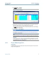
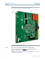
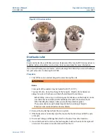
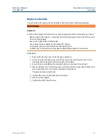
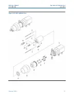
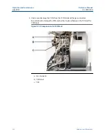
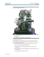
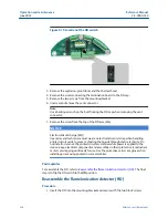
Figure 5-5: XA series valves
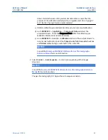
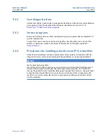
Overhaul a valve

Note

Rosemount valves have a lifetime warranty. Replacement factory-built XA Series valves are
available. Call your local Emerson Customer Care representative for more information.

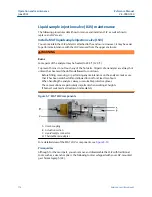
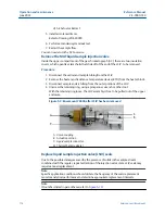
If you are overhauling a six-port valve, refer to drawing #CE-22260; If you are overhauling a
ten-port valve, refer to drawing #CE-22300.
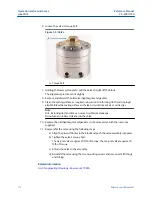
Procedure

1. Shut off the carrier and sample gas streams entering the unit.

 WARNING

Burns

Some parts of the analyzer may be heated to 248 °F (120 °C).

To prevent burns, do not touch any of the hot parts. All parts of an analyzer are
always hot unless it has been switched off and allowed to cool down.

Before fitting, removing, or performing any maintenance on the analyzer, make
sure that it has been switched off and allowed to cool for at least two hours.
When handling the analyzer, always use suitable protective gloves.
These precautions are particularly important when working at heights.
If burned, seek medical treatment immediately.

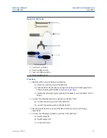
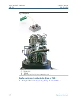
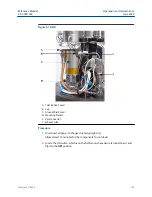
2. Remove the top hat heater from the oven system.
3. If the faulty valve is not easily accessible, loosen the thumb screw and tilt the oven

on its side.

4. Disconnect tubing and fittings that attach to the valve from other locations.
5. Use an Allen wrench to remove the two baseplate bolts on the valve to be replaced

or serviced. The valve can now be removed from the GC.

Reference Manual 

Operation and maintenance

2-3-9000-744

June 2022

Rosemount 700XA

111

Содержание Rosemount 700XA

Страница 1: ...Reference Manual 2 3 9000 744 Rev L June 2022 Rosemount 700XA Gas Chromatograph ...

Страница 2: ...ds or firmware found by Seller to be defective or refund the purchase price of the defective portion of the Goods Services All replacements or repairs necessitated by inadequate maintenance normal wear and usage unsuitable power sources unsuitable environmental conditions accident misuse improper installation modification repair storage or handling or any other cause not the fault of Seller are no...

Страница 3: ...y injure personnel Before opening the analyzer disconnect all electrical power and ensure that the area is free of explosive gases Keep cover tight while circuits are live Use cables or wires suitable for the marked T ratings Cover joints must be cleaned before replacing the cover Conduit runs to the enclosure must have sealing fitting adjacent to enclosure WARNING Power A suitable APPROVED switch...

Страница 4: ...to protecting your system Restrict physical access by unauthorized personnel to protect end users assets This is true for all systems used within the facility NOTICE Replaceable parts Only a few parts inside the device are replaceable Only trained service personnel should replace parts All replacement parts must be authorized by Emerson to ensure product certification compliance NOTICE Equipment d...

Страница 5: ... TCD for the detection of trace compounds The FID requires a polarization voltage and its output is connected to the input to a high impedance amplifier an electrometer The sample of gas to be measured is injected into the burner with a mixture of hydrogen and air to maintain the flame FPD Flame photometric detector The FPD is used to analyze gas compound impurities such as sulfur phosphorous and ...

Страница 6: ...TxD TD or Sout Transmit data or signal out 6 ...

Страница 7: ...nts 47 4 3 Gas chromatograph wiring 51 4 4 Electrical installation 55 4 5 Leak checking and purging for first calibration 95 4 6 Start up the system 98 Chapter 5 Operation and maintenance 101 5 1 Warning and notice 101 5 2 Start a 2 point calibration 101 5 3 Troubleshooting and repair 102 5 4 Routine maintenance 102 Chapter 6 Troubleshooting 183 6 1 Hardware alarms 183 6 2 No power to flame photom...

Страница 8: ...etric detector µFPD 267 C 1 Configure the micro flame photometric detector µFPD 268 Appendix D Recommended spare parts 271 D 1 Recommended spare parts for Rosemount 700XA thermal conductivity detector TCD analyzers 271 D 2 Recommended spare parts for Rosemount 700XA flame ionization detector FID thermal conductivity detector TCD analyzers 272 D 3 Recommended spare parts for Rosemount 700XA flame i...

Страница 9: ...of various certification agencies for use in hazardous environments See the certification tag on the GC for specific details about agency approvals 1 1 1 Analyzer assembly The analyzer assembly includes Columns Thermal conductivity detectors TCDs Flame ionization detectors FIDs Flame photometric detector FPD Preamplifier Preamplifier power supply Stream switching valves Analytical valves Solenoids...

Страница 10: ...s area Emerson provides serial and Ethernet communication links to connect the analyzer to the PC and to connect to other computers and printers in a safe area 1 1 3 Sample conditioning system SCS The optional sample conditioning system is located between the process stream and the sample inlet which is often mounted below the gas chromatograph GC The standard SCS configuration includes a stream s...

Страница 11: ... packing that is either an active solid or an inert solid support that is coated with a liquid phase absorption partitioning 2 A mobile phase carrier gas moves the sample gas through the column 3 The selective retardation of the components takes place in the column causing each component to move through the column at a different rate This separates the sample into its constituent gases and vapors ...

Страница 12: ...GC firmware Rosemount MON2020 software The RTOS firmware and the application configuration software are installed when the Rosemount 700XA is shipped The application configuration is tailored to the customer s process and shipped on a USB stick The hardware and software are tested together as a unit before the equipment leaves the factory Rosemount MON2020 communicates with the GC and can be used ...

Страница 13: ...tiated or controlled by Rosemount MON2020 include but are not limited to the following Valve activations Timing adjustments Stream sequences Calibrations Baseline runs Analyses Halt operation Stream detector heater assignments Stream component table assignments Stream calculation assignments Diagnostics Alarm and event processing Event sequence changes Component table adjustments Calculation adjus...

Страница 14: ...consists of a balanced bridge network with heat sensitive thermistors in each leg of the bridge Each thermistor is enclosed in a separate chamber of the detector block One thermistor is designated the reference element and the other thermistor is designated the measurement element See Figure 1 2 for a schematic diagram of the TCD Overview Reference Manual June 2022 2 3 9000 744 14 Emerson com Rose...

Страница 15: ...y nulled The analysis begins when the sample valve injects a fixed volume of sample into the column The continuous flow of carrier gas moves the sample through the column As successive components elute from the column the temperature of the measurement element changes The temperature change unbalances the bridge and produces an electrical output proportional to the component concentration The diff...

Страница 16: ...ne drift The signals from the preamplifier are sent to the electronic assembly for component concentration computation recording or viewing on a personal computer PC with Rosemount MON2020 1 4 2 Flame ionization detector FID Another detector available for the Rosemount 700XA is the flame ionization detector FID The FID requires a polarization voltage and its output is connected to the input with a...

Страница 17: ...otomultiplier tube PMT and processed by the signal processor The response to phosphorus is linear and quadratic to sulfur The Emerson µFPD solution consists of three key parts burner fiber cable and PMT electronics The hydrogen and air in the burner help to burn the sample containing sulfur components The light emitted from the chemical reaction is then transmitted using the fiber cable from the o...

Страница 18: ...Figure 1 5 µFPD burner front view A µFPD burner Overview Reference Manual June 2022 2 3 9000 744 18 Emerson com Rosemount ...

Страница 19: ...Figure 1 6 µFPD burner back view A µFPD burner B Fiber cable Reference Manual Overview 2 3 9000 744 June 2022 Rosemount 700XA 19 ...

Страница 20: ...Figure 1 7 µFPD burner side view A µFPD burner and cable Overview Reference Manual June 2022 2 3 9000 744 20 Emerson com Rosemount ...

Страница 21: ...e The electrometer will make between one and five ignition attempts if necessary You can select the number of ignition attempts on the Hardware Detector screen If the electrometer does not succeed in igniting then the GC shuts off the hydrogen triggers an alarm and waits for attention from the operator Related information Micro flame photometric detector µFPD 1 4 4 Micro flame photometric detector...

Страница 22: ...Figure 1 9 Electronics module exploded view A Apply thermal compound to both sides Overview Reference Manual June 2022 2 3 9000 744 22 Emerson com Rosemount ...

Страница 23: ...ain board This board is the vital part of the µFPD electronics module It controls the temperature of the TEC provides power to the igniter monitors the flame temperature and digitizes the PMT signal and transmits to the main central processing unit CPU using CAN bus Reference Manual Overview 2 3 9000 744 June 2022 Rosemount 700XA 23 ...

Страница 24: ... cross section A Liquid sample B Air supply four way action C Thermal barrier adapter flange polyether ether ketone PEEK D O ring E Heater element Figure 1 12 LSIV The LSIV penetrates the wall of the lower compartment and is held in place by a retaining ring Overview Reference Manual June 2022 2 3 9000 744 24 Emerson com Rosemount ...

Страница 25: ...alytic converter 1 4 7 Data acquisition Every second the controller assembly takes exactly 50 equally spaced data samples i e one data sample every 20 milliseconds As a part of the data acquisition process groups of incoming data samples are averaged together before the result is stored for processing Non overlapping groups of 50 samples are averaged and stored and thus reduce the effective incomi...

Страница 26: ...andled This is done by testing each termination point to see if the region immediately following it satisfies the criteria of a baseline A baseline region must have a slope detector value less than the magnitude of the baseline constant for a number of sequential points When a baseline region is found this terminates a sequence of peaks A zero reference line for peak height and area determination ...

Страница 27: ...stem through calibration procedures with a calibration gas mixture that has known concentrations The response factor calculation using the external standard is where ARFn Area response factor for component n in area per mole percent Arean Area associated with component n in calibration gas Caln Amount of component n in mole percent in calibration gas Htn Peak height associated with component n mol...

Страница 28: ...or each analysis by using the following equations where ARFn Area response factor for component n in area per mole percent Arean Area associated with component n in unknown sample CONCn Concentration of component n in mole percent Htn Peak height associated with component n mole percent in unknown sample HRFn Peak height response factor for component n Component concentrations may also be input th...

Страница 29: ... in mole percent for each k component CONCn Non normalized concentration of component n in mole percent k Number of components to be included in the normalization Note The average concentration of each component will also be calculated when data averaging is requested Reference Manual Overview 2 3 9000 744 June 2022 Rosemount 700XA 29 ...

Страница 30: ...Overview Reference Manual June 2022 2 3 9000 744 30 Emerson com Rosemount ...

Страница 31: ...ided into two compartments that together house the gas chromatograph s GC s major components This GC is designed for hazardous locations Figure 2 1 Rosemount 700XA Gas Chromatograph A Upper compartment B Lower compartment C Front panel assembly D Mechanical regulators E Sampling system optional Reference Manual Equipment description and specifications 2 3 9000 744 June 2022 Rosemount 700XA 31 ...

Страница 32: ...perator interface LOI Figure 2 2 8 stream switch panel left and 18 stream switch panel right Switch panel The switch panel contains a network of On Off switches that allow the operator to manually control the gas chromatograph s GC s stream and analytical valves Figure 2 3 Eight stream switch panel Equipment description and specifications Reference Manual June 2022 2 3 9000 744 32 Emerson com Rose...

Страница 33: ...osition the switch is neither flipped up nor down ON The valve turns on and remains on until the operational mode is changed To set a valve to ON mode set its switch on th switch panel to the down position Figure 2 5 Status LEDs Top of switch panel The switch panels also contain the following status lights that allow you to monitor the GC s condition Working Turns green when the GC is in Analysis ...

Страница 34: ...mount MON2020 detects the FID and FPD statuses The operator can ignite the flame remotely using Rosemount MON2020 or manually light the flame Figure 2 8 Rosemount MON2020 status indicators Note During GC start up all LEDs turn on for approximately ten seconds Equipment description and specifications Reference Manual June 2022 2 3 9000 744 34 Emerson com Rosemount ...

Страница 35: ...er Figure 2 9 LOI The LOI includes the following features Color LCD display with VGA 640 x 480 pixels resolution ASCII text and graphics modes Adjustable auto backlighting Eight infrared activated touch screen keys that eliminate the requirement for a magnetic pen Complete GC status control and diagnostics including full chromatogram display Reference Manual Equipment description and specification...

Страница 36: ...the front panel or local operator interface LOI and in Rosemount MON2020 Flame ionization detector FID The optional FID detects trace levels of hydrocarbons Flame photometric detector FPD The optional FPD which detects trace levels of sulfur compounds can be used in place of a TCD installed as a side car component For more information refer to the FPD for Gas Chromatographs Hardware Reference Manu...

Страница 37: ... the cover Conduit runs to the enclosure must have sealing fitting adjacent to enclosure The card cage holds the specialized PCBs that plug into the backplane The following PCBs are housed in the card cage Preamplifier board Central processing unit CPU board Base in out I O board Heater solenoid board The card cage also has four additional slots for the following optional PCBs A second preamplifie...

Страница 38: ...gas flow through the gas chromatograph s columns as well as the pressure of the flame ionization detector FID or flame photometric detector FPD air and fuel H2 if installed The regulators and gauges are typically located on front of the analyzer below the electronics enclosure Figure 2 10 Regulators and gauges Equipment description and specifications Reference Manual June 2022 2 3 9000 744 38 Emer...

Страница 39: ...tometric detector FPD 32 F 0 C to 122 F 50 C Hazardous area certifications hardware dependent USA and Canada Class I Zone 1 Ex AEx db IIC Gb T6 T4 T3 Class I Division 1 Groups B C and D IP66 EU ATEX and IECEx Ex db IIC Gb T6 T4 T3 Ta 4 F 20 C to 140 F 60 C SIRA 08ATEX 1328X IECEx SIR 08 0093X Consult factory for additional product certifications available Table 2 1 Approval temperature ratings T6 ...

Страница 40: ...gital outputs Five outputs user assignable Form C and electro mechanically isolated 24 Vdc Communication optional Four expansion slots available for additional communications Each slot has the capacity to add one of the following Four analog inputs isolated card Four analog outputs isolated card Eight digital inputs isolated card Five digital outputs isolated card One RS 232 RS 422 or RS 485 seria...

Страница 41: ...s clock configurations Peak Integration Fixed time or auto slope and peak identification Update retention time upon calibration or during analysis Cyber security Encrypted SSL communication between gas chromatograph GC and Rosemount MON2020 2 2 4 Corrosion protection Type Specification Enclosure material Copper free and aluminum coated with industrial grade powder coat suitable for high humidity a...

Страница 42: ...le time Daily averages 365 1 year Weekly averages 58 1 year Monthly averages 12 1 year Variable averages 250 1 N A Every run up to 250 variables 250 1 N A Alarm logs 1000 N A Event logs 1000 N A 1 Changed from 2 0 x release 2 The gas chromatograph GC can store final calibration and validation chromatograms for a year provided that no more than one calibration validation is run per day and the cycl...

Страница 43: ...ovides serial and Ethernet communication links to connect the analyzer to the PC and to connect to other computers and printers in a safe area Allow a minimum of 3 ft 0 91 m in front of the GC for operator access Ensure that exposure to radio frequency interference RFI is minimal 3 2 Unpack the gas chromatograph GC Unpack and inspect the Rosemount 700XA upon receipt WARNING This device is heavy eq...

Страница 44: ...ll provide disposition instructions as soon as possible If you have any questions regarding the claim process contact your Emerson Customer Care representative for assistance 6 Only proceed to install and start up the GC if all required materials are on hand and free from obvious defects 7 If your GC is configured with an flame ionization detector FID or flame photometric detector FPD remove the v...

Страница 45: ...romatographic analysis Coalescing filter Membrane filter in stainless steel tubing For connecting calibration gas to the GC For connecting carrier gas to the GC For connecting stream gas to the GC Sulfinert tubing required if sulfur components are present in calibration gas Heat tracing as required for sample transport and calibration lines Miscellaneous tube fittings tubing benders and tubing cut...

Страница 46: ...computers and printers in a safe area Use a Windows based PC and either a direct or remote communications connection to interface with the GC NOTICE Consult the Rosemount MON2020 Software for Gas Chromatographs Reference Manual for more information The GC comes with an Ethernet port on the backplane factory wired with an RJ 45 connector Related information Connect directly to a personal computer P...

Страница 47: ... Ensure that the connections to the enclosure meet local standards 3 Use approved seals either cable glands or conduit seals a Install conduit seals within 3 in 76 mm of the enclosure b Seal unused openings with approved blanks plugs Threads for these openings are M32 x 1 5 4 Remove any packing materials before powering up the GC 5 6 WARNING Hazardous area explosion hazard Failure to follow this w...

Страница 48: ...ement is the wall mount If you specify Wall Mount on the sales order Emerson will ship the GC with a wall mount installation kit Four locations on the mounting ears are available for support WARNING The GC is heavy and has a high potential of injuring personnel or damaging equipment Anchor the GC solidly before making electrical connections Until all bolts are tight ensure that the GC is supported...

Страница 49: ...with washers and then tighten all the bolts 4 2 2 Mount the gas chromatograph GC to a pole The pole mount arrangement uses an additional plate and spacers to allow the necessary clearance for nuts If you specify Pole Mount on the sales order Emerson will provide the necessary hardware WARNING The GC is heavy and has a high potential of injuring personnel or damaging equipment Anchor the GC solidly...

Страница 50: ... tighten all bolts 8 Adjust the lower bracket to align the bolts with the plate Tighten the bolts 4 2 3 Mount the gas chromatograph GC on the floor If you specify Floor Mount in the sales order Emerson sends the floor mounting arrangement pre assembled with the GC The arrangement includes an additional support stand that is intended to be anchored to a floor or an instrument pad The base rails hav...

Страница 51: ...tions For power feed distances up to 250 ft 76 m use 14 AWG 18 metric wire gauge MWG stranded For power feed distances 250 ft 76 m to 500 ft 152 m use 12 AWG 25 MWG stranded For power feed distances 500 ft 152 m to 1 000 ft 305 m use 10 AWG 30 MWG stranded 4 3 2 Signal wiring Follow these general precautions for field wiring digital and analog input output I O lines For shielded signal conducting ...

Страница 52: ...s apply in the US Length Wire 15 ft 4 57 m or less 8 AWG stranded insulated copper 15 ft 4 57 m to 30 ft 9 14 m 6 AWG stranded insulated copper 30 ft 9 14 m to 100 ft 30 48 m 4 AWG stranded insulated copper All interior enclosure equipment grounding conductors must be protected by metal conduit External equipment that is connected to the GC should be powered via isolation transformers to minimize ...

Страница 53: ...some other approved means that does not deform the conduit ends or leave sharp edges Coat all conduit fitting threads including factory cut threads with a metal bearing conducting grease prior to assembly Temporarily cap the ends of all conduit runs immediately after installation to prevent accumulation of water dirt or other contaminants If necessary swab out conduits prior to installing the cond...

Страница 54: ... Dryers and filters Use small sizes to minimize time lag and prevent back diffusion Install a minimum of one filter to remove solid particles Most applications require fine element filters upstream of the gas chromatograph GC The GC includes a 2 micron filter Use ceramic or porous metallic type filters Do not use cork or felt filters NOTICE Install the probe regulator first immediately followed by...

Страница 55: ...ct power supply WARNING Electrical hazard Failure to follow this warning may result in injury or death to personnel or cause damage to equipment Ensure that the 24 Vdc input power source is switched Off before connecting the wires Ensure that the 24 Vdc power supply is safety extra low voltage SELV compliant by suitable electrical separation from other circuits Reference Manual Installation and st...

Страница 56: ...tograph GC prior to wiring to determine if it is equipped for DC power Procedure 1 Locate the plug together termination block inside the electronics enclosure Figure 4 6 24 Vdc power connection on the backplane Installation and start up Reference Manual June 2022 2 3 9000 744 56 Emerson com Rosemount ...

Страница 57: ...sconnect the factory installed ground wire The backplane board that connects to the 24 Vdc is protected from lead reversal by the use of blocking diodes If the red and black leads are inadvertently reversed no damage will occur however the system will not have power 3 Connect the DC power leads to the power disconnect switch that should be properly fused The recommended fuse size is 8 amps Referen...

Страница 58: ...block WARNING Failure to follow this warning may result in injury or death to personnel or cause damage to equipment Do not connect the AC power leads without first ensuring that the AC power source is switched Off NOTICE Failure to observe this precaution may cause damage to equipment Do not apply electrical power to the GC until all interconnections and external signal connections have been veri...

Страница 59: ...ads in through the left entry on the bottom of the enclosure 3 If necessary at remote locations connect the GC chassis ground wire to an external copper ground rod Related information Signal wiring Reference Manual Installation and start up 2 3 9000 744 June 2022 Rosemount 700XA 59 ...

Страница 60: ...to wind protect the exposed vent with a metal shield Use in or in tubing for vent lines longer than 10 ft 3 05 m NOTICE Do not discard the vent line plugs They are useful when leak checking the gas chromatograph GC and its sample or gas line connections At this stage in the installation the measure vent MV lines labeled on the side of the GC should remain plugged until the GC has been checked for ...

Страница 61: ... Use a dual stage regulator with high side capacity of 3 000 psig 206 84 barg and low side capacity of 150 psig 10 34 barg Carrier gas is fed from two bottles for carrier gas plumbing 3 Connect calibration standard gas to the GC When installing the calibration standard gas line ensure that the correct tubing connection is made Use in stainless steel tubing to connect calibration standard gas unles...

Страница 62: ...l lines have been installed proceed with leak checking the carrier and sample lines 4 4 4 Maximum effective distance by communication protocol type Table 4 1 lists the maximum distance at which the indicated protocol can transmit data without losing effectiveness If you need longer runs use a repeater or other type of extender to maintain the protocol s efficiency Table 4 1 Maximum distance for ea...

Страница 63: ...OTICE Analog modems will only work with PSTN phone lines Analog modems will not work with VOIP networks The following four LEDs are provided on the modem for troubleshooting RI Ring indicator This LED flashes when it senses a ring This LED should only flash once per connection because the modem automatically answers on the first ring CD Carrier detect This LED glows green while connected to Rosemo...

Страница 64: ...5 Set the Baud Rate for the analog modem card to 57600 16 Make note of the I O slot s Modbus Id 17 Click Save 18 Click OK to close the Communication window 19 Disconnect from the GC 4 4 7 Connect directly to a personal computer PC using the gas chromatograph s GC s Ethernet1 port The GC s DHCP server feature and its Ethernet1 port on the backplane at J22 allows you to connect directly to the GC Th...

Страница 65: ...eck the status that displays beneath the Local Area Connection It should show the status as Connected The PC is now capable of connecting to the GC If the status is Disconnected it may be that the PC is not configured to accept IP addresses therefore do the following 4 Right click the Properties icon The Local Area Connection Properties window displays 5 Scroll to the bottom of the Connection list...

Страница 66: ...nect to GC window displays 2 Locate the default Direct DHCP under the GC Name column This GC directory is created automatically when Rosemount MON2020 is installed You can rename the GC but do not change the IP address that it references 192 168 135 100 3 Click the associated Ethernet button Rosemount MON2020 prompts you to enter a user name and password 4 Enter your user name and password 5 Rosem...

Страница 67: ...the LOI is communicating with the GC 2 Check that the SW1 switch is in the On position 3 Check the following connections a If you are using a Ethernet straight through cable ensure that the personal computer PC has an Ethernet network interface card with auto MDIX b If your Ethernet network interface card does not support auto MDIX ensure that you are using an Ethernet crossover patch cable Refere...

Страница 68: ...that your network adapter is enabled a Go to Start Control Panel Network Connections b Check the status of the Local Area Connection icon If the status appears as Disabled right click the icon and select Enable from the context menu 5 Do the following to try to repair the network connection a Go to Start Control Panel Network Connections b Right click the Local Area Connection icon and select Repa...

Страница 69: ... Figure 4 13 J23 serial port A J23 port To set up the PC for the direct connection Procedure 1 Install the communications cable between two computers a Navigate to Start Control Panel and select the Phones and Modem Options icon The Phones and Modem Options dialog window displays b Select the Modem tab and click Add The Add Hardware Wizard displays c Select the Don t detect my modem I will select ...

Страница 70: ...Direct Connection modem a Go to File GC Directory The GC Directory window displays b Select Add from the GC Directory window s File menu A New GC row is added to the bottom of the table c Select the New GC text and type a new name for the GC connection d Select the new GC s Direct check box e Click the Direct button located at the bottom of the GC Directory window The Direct Connection Properties ...

Страница 71: ... terminal at TB11 on the backplane that you can connect to with a static Internet protocol IP address All that is needed is a PC typically a notebook computer and a two wire twisted pair CAT5 Ethernet cable with one of its plugs removed to expose the wires Figure 4 14 Crimped CAT5 cable NOTICE The GC can be connected or remain connected to the local network on Ethernet2 TB11 on the backplane while...

Страница 72: ...al wiring scheme Figure 4 17 shows how to wire a CAT5 cable without the RJ45 plug Figure 4 16 Field wiring to TB11 Figure 4 17 CAT5 wiring to TB11 2 Once you have wired the cable to the Ethernet terminal plug the other end into a PC or a wall jack Installation and start up Reference Manual June 2022 2 3 9000 744 72 Emerson com Rosemount ...

Страница 73: ...at TB11 Enter the appropriate values in the Ethernet2 IP Address the Ethernet 2 Subnet and the Default Gateway fields b The RJ45 Ethernet port at J22 Enter the appropriate values in the Ethernet1 IP Address the Ethernet1 Subnet and the Default Gateway fields Note See your information technology IT staff to obtain IP subnet and gateway addresses Important To configure a Ethernet IP address using th...

Страница 74: ...J22 b Move dip switch 1 to its left position Off This disables the DHCP server 8 To connect to the GC a Start Rosemount MON2020 and select File GC Directory The GC Directory window displays b Select Add Rosemount MON2020 adds a new GC profile to the end of the table Note You can name the GC s profile as well as add a short description c Select the new profile and click Ethernet Enter the GC s stat...

Страница 75: ...cause serious personal injury or death The equipment operates using mains voltage that is dangerous to life Make sure that the circuit breakers are set to OFF and tagged off before removing the top cover or opening the front cover WARNING Explosion Failure to de energize the analyzer may cause an explosion and severely injure personnel Before opening the analyzer disconnect all electrical power an...

Страница 76: ... digital input output I O lines away from the sensitive detector lines on the left side of the backplane and away from the analog inputs and outputs There are connections for five digital inputs on the backplane at TB7 as indicated in Table 4 2 Table 4 2 Discrete digital inputs at TB7 TB7 Function Pin 1 Digital input 1 Pin 2 Digital input return Pin 3 Digital input 2 Pin 4 Digital input return Pin...

Страница 77: ...ir cables for in out IO signal wiring The module s terminal blocks accept wire sizes between 12 and 22 American wire gauge AWG Allow some slack when making connections to prevent strain NOTICE Failure to follow this notice may cause a short circuit and damage equipment Allow only a minimal amount of bare wire to prevent short circuits 2 Insert the exposed end into the clamp beneath the termination...

Страница 78: ...nal Label Definition 1 1 Channel 1 Positive 2 2 Channel 2 Positive 3 3 Channel 3 Positive 4 4 Channel 4 Positive 5 5 Channel 5 Positive 6 6 Channel 6 Positive 7 7 Channel 7 Positive 8 8 Channel 8 Positive 9 COM Common 10 COM Common Installation and start up Reference Manual June 2022 2 3 9000 744 78 Emerson com Rosemount ...

Страница 79: ...le 4 4 lists the discrete digital output function for each pin on the TB3 connector Table 4 4 Discrete digital outputs on TB3 TB3 Function Pin 1 Normally closed NC1 DIG_OUT NC1 Pin 2 ARM1 DIG_OUT ARM1 Pin 3 Normally open NO1 DIG_OUT NO1 Pin 4 NC2 DIG_OUT NC2 Pin 5 ARM 2 DIG_OUT ARM2 Pin 6 NO2 DIG_OUT NO2 Pin 7 NC3 DIG_OUT NC3 Pin 8 ARM3 DIG_OUT ARM3 Reference Manual Installation and start up 2 3 9...

Страница 80: ...n ARM and normally open NO Related information List of engineering drawings Rosemount 700XA Optional discrete digital inputs DI When plugged into one of the optional card slots in the card cage the Emerson ROC800 DI card provides eight additional discrete digital inputs The discrete digital inputs can monitor the status of relays open collector or open drain type solid state switches and other two...

Страница 81: ...n out I O modules Wire a ROC800 digital output DO module Figure 4 23 Discrete discrete output wiring A Control B Discrete device externally powered Reference Manual Installation and start up 2 3 9000 744 June 2022 Rosemount 700XA 81 ...

Страница 82: ...f the wire to a maximum length of 0 25 in 6 4 mm NOTICE We recommend twisted pair cables for in out IO signal wiring The module s terminal blocks accept wire sizes between 12 and 22 American wire gauge AWG Allow some slack when making connections to prevent strain NOTICE Failure to follow this notice may cause a short circuit and damage equipment Allow only a minimal amount of bare wire to prevent...

Страница 83: ... can be installed into one of the optional slots in the card cage Analog inputs on the backplane There are two analog input connections on the backplane at terminal block 10 TB10 Figure 4 24 TB10 on the backplane Table 4 5 Analog inputs TB10 TB10 Function Pin 1 AI_1 Pin 2 AI_1 Pin 3 AI_2 Pin 4 AI_2 Reference Manual Installation and start up 2 3 9000 744 June 2022 Rosemount 700XA 83 ...

Страница 84: ...nalog input switches that are located on the base input output I O board These analog inputs are set to accept a current 4 20 mA source Figure 4 26 Factory settings for analog input switches Use the Hardware Analog Inputs menu in Rosemount MON2020 to configure the analog inputs Note To set an analog input to accept a voltage 0 10 VDC source flip the appropriate switch in the opposite direction fro...

Страница 85: ...ocate SW2 on the base I O board and push the switches up toward the card ejector to set the analog input to voltage push the switches down away from the card ejector 5 Replace the base I O board in the card cage 6 Close and fasten the electronic enclosure door 7 Apply power to the GC 8 Select Hardware Analog Inputs The Analog Inputs window displays 9 To set the analog input to current select mA fr...

Страница 86: ...output Optional analog inputs AI When plugged into one of the optional card slots on the card cage the ROC800 AI 16 card provides four additional analog inputs The AI channels are scalable but are typically used to measure either a 4 20 mA analog signal or a 1 5 Vdc signal If required the low end of the AI module s analog signal can be calibrated to zero For more information see Analog Input Modul...

Страница 87: ...o prevent shorting the boards through static electricity Do not install or remove the printed circuit assemblies while power is applied to the device Keep electrical components and assemblies in their protective conductive carriers or wrapping until ready for use Use the protective carrier as a glove when installing or removing printed circuit assemblies Reference Manual Installation and start up ...

Страница 88: ...connections to prevent strain NOTICE Electrical hazard Exposing bare wires may cause a short circuit and damage equipment Keep exposed bare wires to a minimum 2 Insert the exposed end into the clamp beneath the termination screw 3 Tighten the screw There are two dip switches on the terminal block side of the module that can be used to set a 250 Ω resistor in or out of circuit for each analog input...

Страница 89: ... decade box or comparable equipment to the RTD terminals of the ROC card 5 Click Calibrate 6 Enter a value for Set Zero after stabilization 7 Enter a value for Set Span after stabilization 8 Enter values for up to three Midpoints one at a time or click Done if you are not configuring midpoints 9 Click OK to close the main calibration window and unfreeze the associated inputs Postrequisites To cali...

Страница 90: ... also shows how to wire up to two analog inputs Figure 4 30 Wiring for six analog outputs Figure 4 31 shows the factory settings for the analog output switches that are located on the base in out I O board Figure 4 31 Factory settings for analog output switches Installation and start up Reference Manual June 2022 2 3 9000 744 90 Emerson com Rosemount ...

Страница 91: ...ng isolation between channels Figure 4 32 Wiring for customer powered analog outputs A Backplane B Customer devices C Analog outputs D Inputs Figure 4 32 shows the settings for the analog outputs switches located on the base input output I O board that are necessary to provide power to each analog output while maintaining isolation between channels Reference Manual Installation and start up 2 3 90...

Страница 92: ...te Connect ROC800 analog output AO module to a field device Procedure 1 Expose the end of the wire to a maximum length of 0 25 in 6 4 mm Note We recommend using twisted pair cables for in out I O signal wiring The module s terminal blocks accept wire sizes between 12 and 22 American wire gauge AWG Expose minimal bare wire to prevent short circuits Allow some slack when making connections to preven...

Страница 93: ... Configuration screen You can use the Filter Selections drop down list to filter by the type of hardware you are interested in The options are All Detectors Valves Discrete Output EPC Heaters By default All is selected and all types of hardware are displayed To filter by a certain type of hardware select it from the list Then only rows with the selected hardware will be displayed 3 Click Discrete ...

Страница 94: ... If enabled the GC analyzes the calibration gas as an unknown stream and computes its energy value The GC then compares this value to the Cal Gas Cert CV and determines if the calibration gas s energy value is within the CV Check Allowed Deviation If it isn t the GC triggers the Energy Value Invalid alarm The following conditions must be met before the GC can perform a EV Check The EV Check flag o...

Страница 95: ...led MV vent line if it is open Leave the SV or sample vent line open or unplugged 2 Slowly pressurize each line in turn then block in the line making sure the pressure holds For example the carrier gas line should be slowly brought up to 100 psig 6 89 barg two percent with the dual stage regulator at the carrier gas cylinder and the actuation pressure should be 100 psig 6 89 barg maximum 3 After t...

Страница 96: ...hese points about flow diagrams Port to port flow paths are indicated by solid or dashed lines on the valve symbol in the drawing A dashed line indicates flow direction when the valve is On or energized A solid line indicates flow direction when the valve is Off or not energized 4 5 3 Purge carrier gas lines Prerequisites Purging carrier and calibration gas lines requires power and a personal comp...

Страница 97: ...0 Software for Gas Chromatographs Reference Manual for more information Note You can also perform Step 6 through Step 8 with the local operator interface LOI Important Emerson recommends a continuous operation without sample gas for a period of four to eight hours or overnight during which no changes should be made to the settings described in Step 1 through Step 7 4 5 4 Purge calibration gas line...

Страница 98: ... block valve is usually located on the lower right hand corner of the front panel Refer to the Rosemount MON2020 Software for Gas Chromatographs Reference Manual for instructions on selecting streams 4 Open the calibration gas bottle valve 5 Increase the outlet pressure to 15 psig 1 03 barg plus or minus five percent at the calibration gas bottle regulator 6 Close the calibration gas bottle valve ...

Страница 99: ...e Go to MON2020 Control Calibration and select the analysis stream to run a manual calibration Select the Purge stream for 60 seconds checkbox and Normal calibration type radio button then click OK NOTICE Consult the Rosemount MON2020 Software for Gas Chromatographs Reference Manual for more information 2 Select Control Auto Sequence to start auto sequencing of the line gas stream s NOTICE Consult...

Страница 100: ...Installation and start up Reference Manual June 2022 2 3 9000 744 100 Emerson com Rosemount ...

Страница 101: ...ions gases called the low calibration gas LCG should have a lower concentration of the components than the other calibration gas which is called the high calibration gas HCG The GC can then compute the coefficients for the 2 point 2 Pt exponential power fit by doing a single level calibration on these individual LCG and HCG streams Procedure 1 Start Rosemount MON2020 and press F6 to open the Compo...

Страница 102: ...of the Rosemount 700XA enables a maintenance technician to schedule replacement of gas cylinders at a convenient time and allows quick troubleshooting and repair when necessary Also create a diagnostic file which contains calibration and analysis chromatograms alarm and event logs analysis reports and the complete configuration file and file it with the checklist furnishing a positive dated record...

Страница 103: ...o find the default measurements for the parameters on the checklist use Rosemount MON2020 to view the GC s parameter list Reference Manual Operation and maintenance 2 3 9000 744 June 2022 Rosemount 700XA 103 ...

Страница 104: ...Figure 5 1 Sample Maintenance Checklist Operation and maintenance Reference Manual June 2022 2 3 9000 744 104 Emerson com Rosemount ...

Страница 105: ...r handling printed circuit PC assemblies Printed circuit assemblies contain complementary metal oxide semiconductor CMOS integrated circuits which can be damaged if the assemblies are not properly handled NOTICE Electrostatic discharge ESD Operators and technicians must wear an electrostatic wrist strap when handling printed circuit cards to prevent shorting the boards through static electricity D...

Страница 106: ...ation When connected to the gas chromatograph GC via Rosemount MON2020 select Hardware Detectors to access the Detectors dialog Refer to the Rosemount MON2020 Software for Gas Chromatographs Reference Manual for additional configuration details Operation and maintenance Reference Manual June 2022 2 3 9000 744 106 Emerson com Rosemount ...

Страница 107: ...Figure 5 3 Rosemount MON2020 Detectors window Halt the analysis Control Halt F3 Reference Manual Operation and maintenance 2 3 9000 744 June 2022 Rosemount 700XA 107 ...

Страница 108: ...tch should be set to ON 5 4 6 Replace the central processing unit CPU Procedure 1 Save the gas chromatograph GC configuration file In MON2020 go to File Save Configuration to PC 2 Power down the GC 3 Open the GC cover 4 Remove the clear plastic cover that holds the boards in place 5 Remove the CPU board CAUTION ELECTROSTATIC DISCHARGE ESD HANDLING PRECAUTIONS REQUIRED CPU boards are sensitive elec...

Страница 109: ...OFF away from the dot D Turn SW6 OFF away from the dot Note Rosemount 700XA GCs are tagged with CPU board part number 7A00555G02 7 Install the new CPU board in the card cage Ensure the board is seated firmly in place 8 Place the clear plastic cover back over the boards 9 Close the GC cover Reference Manual Operation and maintenance 2 3 9000 744 June 2022 Rosemount 700XA 109 ...

Страница 110: ... Go to Control Auto Sequence to auto sequence the GC 5 4 7 Repairing and maintaining the valves Only minimal valve repair and maintenance is required e g replacing the diaphragms Required tools for valve maintenance The tools required for performing repair and general maintenance on the Rosemount XA Series valve assemblies are Torque wrench scaled in foot pounds in socket for 10 port valves 7 16 i...

Страница 111: ...hed off and allowed to cool down Before fitting removing or performing any maintenance on the analyzer make sure that it has been switched off and allowed to cool for at least two hours When handling the analyzer always use suitable protective gloves These precautions are particularly important when working at heights If burned seek medical treatment immediately 2 Remove the top hat heater from th...

Страница 112: ... use an oil based cleaner on the valve 10 Replace the old diaphragms and gaskets in the same order with the new ones supplied 11 Reassemble the valve using the following steps a Align the pins with holes in the block and push the valve assembly into place b Tighten the valve s torque bolt The six port valve requires 20 ft lb of torque the ten port valve requires 30 ft lb of torque c Return the val...

Страница 113: ...sure must have sealing fitting adjacent to enclosure Procedure 1 Remove the thermal cover from the upper enclosure 2 Loosen the ultem thumb screw and tilt the oven on its side to gain access to the solenoids that are located on the underside of the ultem 3 Loosen the screws holding the solenoid in place and remove the solenoid 4 Place a small amount of silicone grease on the target device pneumati...

Страница 114: ...emoving or performing any maintenance on the analyzer make sure that it has been switched off and allowed to cool for at least two hours When handling the analyzer always use suitable protective gloves These precautions are particularly important when working at heights If burned seek medical treatment immediately Figure 5 7 MAT LSIV components A Union coupling B Actuation section C Liquid sample ...

Страница 115: ...ngs c Tighten the retaining ring by twisting it clockwise to secure the MAT LSIV to the GC 2 Connect the following internal GC gas lines to the MAT LSIV a Connect the carrier gas line to the MAT LSIV b Connect the sample gas line to the MAT LSIV 3 Place the insulation sleeve around the flash chamber as shown in Drawing DE 20990 4 Connect the following external GC gas lines to the MAT LSIV a Liquid...

Страница 116: ...using a pin spanner wrench or other tool With the retaining ring loose the LSIV assembly is free to be pulled out of the upper enclosure Figure 5 9 Rosemount 700XA after LSIV has been removed A Union coupling B Actuation section C Liquid sample connector D Thermal barrier adapter Replace liquid sample injection valve LSIV seals Due to the possible damage caused by the presence of solids in the sam...

Страница 117: ...Figure 5 10 LSIV exploded view Reference Manual Operation and maintenance 2 3 9000 744 June 2022 Rosemount 700XA 117 ...

Страница 118: ...t 2 See part ID 05 3 See part ID 04 4 Only if required 5 Emerson equipment Procedure 1 Halt sample flow and allow time for the LSIV to cool 2 Remove the actuation portion of the valve by unscrewing the union coupling from the heater section which should remain attached to the gas chromatograph GC Emerson has provided a union coupling wrench for this purpose This will expose the sample flow chamber...

Страница 119: ...nce of each filament using a multimeter A pair of thermistors should give the same resistance reading therefore if a thermistor reading is significantly different from the reading of its mate replace the pair Otherwise the TCD bridge will be unbalanced noisy and drifty Required tools for thermal conductivity detector TCD maintenance A flat head screwdriver is required for removing and replacing TC...

Страница 120: ...1 and TCD 2 retainer nuts and thermistor leads Replace a thermal conductivity detector TCD See drawing DE 22143 in List of engineering drawings Rosemount 700XA Operation and maintenance Reference Manual June 2022 2 3 9000 744 120 Emerson com Rosemount ...

Страница 121: ...ight while circuits are live Use cables or wires suitable for the marked T ratings Cover joints must be cleaned before replacing the cover Conduit runs to the enclosure must have sealing fitting adjacent to enclosure Procedure 1 Disconnect all power to the GC 2 If you have not already done so remove the explosion proof dome and the thermal cover Reference Manual Operation and maintenance 2 3 9000 ...

Страница 122: ...onnectors Be careful not to damage the PTFE washer that is placed between the TCD and the TCD block Figure 5 12 Components of a TCD block a Gas connector b TCD block c TCD Operation and maintenance Reference Manual June 2022 2 3 9000 744 122 Emerson com Rosemount ...

Страница 123: ... the retainer nut To replace the thermistor do the following a Unscrew and release the thermistor leads from the termination block b Unscrew the retainer nut from the TCD block c Remove the PTFE seals as well as the thermistor and its wires from the retainer nut d Remove the PTFE shields from the old thermistor wires and install on the new thermistor wires e Insert a new PTFE seal into the TCD blo...

Страница 124: ...four screws 8 Replace the thermal cover and explosion proof dome 9 Apply power to the GC Remove the flame ionization detector FID The FID has no replaceable parts If it has damage such as as broken resistance temperature device RTD or igniter coil you will need to remove and replace the FID WARNING Explosion Failure to de energize the analyzer may cause an explosion and severely injure personnel B...

Страница 125: ...e Procedure 1 Disconnect all power to the gas chromatograph GC Allow at least 10 minutes for the components to cool down 2 Locate the FID switch which is on the half moon shaped wire terminal board and flip it to the OFF position Reference Manual Operation and maintenance 2 3 9000 744 June 2022 Rosemount 700XA 125 ...

Страница 126: ...o prevent shorting the boards through static electricity Do not install or remove the printed circuit assemblies while power is applied to the device Keep electrical components and assemblies in their protective conductive carriers or wrapping until ready for use Use the protective carrier as a glove when installing or removing printed circuit assemblies Postrequisites To reassemble the FID refer ...

Страница 127: ...tubing nut connectors located at the base of the FID 6 Install the explosion proof cover over the FID assembly and secure to the base with eight bolts Replace igniter thermocouple assembly Figure 5 16 Igniter thermocouple assembly front view A Bulkhead nut B Screws and washers C Fitting D Bulkhead nut E Igniter thermocouple assembly F Igniter connector Reference Manual Operation and maintenance 2 ...

Страница 128: ...he nut then slide the igniter thermocouple assembly and ferrule not shown here out of the µFPD burner through the fitting 6 Slide the bulkhead nut and a new ferrule on the new igniter thermocouple assembly Then slide the µFPD burner through the fitting 7 Align the black plastic edge of the igniter with the end of the nut and gradually tighten the nut to the fitting Keep pushing the igniter toward ...

Страница 129: ... in lb 10 Secure the screws and washers 11 Reconnect the igniter connector Troubleshoot igniter thermocouple assembly Figure 5 18 Igniter thermocouple assembly drawing A Purple igniter B Black igniter C White thermocouple D Red thermocouple Reference Manual Operation and maintenance 2 3 9000 744 June 2022 Rosemount 700XA 129 ...

Страница 130: ...l measure 3 0 to 3 3 Vdc while igniting You can manually ignite with the Detectors pop up window If no voltage is measured you may need to replace the photomultiplier tube PMT module or extension cable 2 Remove black plate Igniter shall glow red while igniting or if you apply 3 Vdc to pins 1 and 2 on burner end Do not apply more than 3 3 Vdc to igniter Do not apply voltage to igniter for more than...

Страница 131: ... may be heated to 248 F 120 C To prevent burns do not touch any of the hot parts All parts of an analyzer are always hot unless it has been switched off and allowed to cool down Before fitting removing or performing any maintenance on the analyzer make sure that it has been switched off and allowed to cool for at least two hours When handling the analyzer always use suitable protective gloves Thes...

Страница 132: ... burner mounting plate to disconnect the cable Figure 5 20 µFPD burner disassembly back view A µFPD burner B µFPD fiber cable clamp C Screws µFPD burner D µFPD fiber cable E Thumb screw Operation and maintenance Reference Manual June 2022 2 3 9000 744 132 Emerson com Rosemount ...

Страница 133: ...connected fiber cable to prevent debris or moisture contamination Figure 5 21 µFPD fiber cable disassembled 5 Remove the two screws from the µFPD burner housing Reference Manual Operation and maintenance 2 3 9000 744 June 2022 Rosemount 700XA 133 ...

Страница 134: ...ove the fiber cable clamp screws and O ring Set aside for reassembly Figure 5 22 µFPD fiber cable clamp disassembly Operation and maintenance Reference Manual June 2022 2 3 9000 744 134 Emerson com Rosemount ...

Страница 135: ...intake and sample lines Figure 5 23 µFPD igniter and intake lines A Igniter thermocouple TC B Air intake port C Hydrogen intake port D Sample intake port Reference Manual Operation and maintenance 2 3 9000 744 June 2022 Rosemount 700XA 135 ...

Страница 136: ...the analyzer may cause an explosion and severely injure personnel Before opening the analyzer disconnect all electrical power and ensure that the area is free of explosive gases Keep cover tight while circuits are live Use cables or wires suitable for the marked T ratings Cover joints must be cleaned before replacing the cover Conduit runs to the enclosure must have sealing fitting adjacent to enc...

Страница 137: ...owed to cool for at least two hours When handling the analyzer always use suitable protective gloves These precautions are particularly important when working at heights If burned seek medical treatment immediately Tools required 7 64 in Allen wrench Phillips screwdriver Flathead screwdriver Procedure 1 Disconnect all power to the unit Allow at least 10 minutes for the components to cool down 2 Re...

Страница 138: ...n the GC Finger tighten the bulkhead nut Figure 5 25 µFPD burner installation A µFPD burner 4 Attach and finger tighten two screws washers on the plastic bracket to center post Operation and maintenance Reference Manual June 2022 2 3 9000 744 138 Emerson com Rosemount ...

Страница 139: ...ith torque of 20 in lb Figure 5 26 µFPD fiber cable clamp assembly 6 Install the fiber cable to the µFPD burner connector and secure with cable clamp Reference Manual Operation and maintenance 2 3 9000 744 June 2022 Rosemount 700XA 139 ...

Страница 140: ...of the µFPD burner housing Figure 5 27 µFPD burner assembly A µFPD burner B µFPD cable clamp C Screws µFPD burner D µFPD fiber cable E Thumb screw Operation and maintenance Reference Manual June 2022 2 3 9000 744 140 Emerson com Rosemount ...

Страница 141: ...make sure that it has been switched off and allowed to cool for at least two hours When handling the analyzer always use suitable protective gloves These precautions are particularly important when working at heights If burned seek medical treatment immediately Figure 5 28 µFPD igniter and intake lines A Igniter thermocouple B Air intake port C Hydrogen intake port D Sample intake port 9 Replace t...

Страница 142: ...prevent burns do not touch any of the hot parts All parts of an analyzer are always hot unless it has been switched off and allowed to cool down Before fitting removing or performing any maintenance on the analyzer make sure that it has been switched off and allowed to cool for at least two hours When handling the analyzer always use suitable protective gloves These precautions are particularly im...

Страница 143: ...om the µFPD burner mounting plate to disconnect the cable Figure 5 29 µFPD burner disassembly A µFPD burner B Fiber cable clamp C Screws µFPD burner D µFPD fiber cable E Thumb screw Reference Manual Operation and maintenance 2 3 9000 744 June 2022 Rosemount 700XA 143 ...

Страница 144: ...pe to the end of the disconnected fiber cable to prevent debris or moisture contamination Figure 5 30 µFPD fiber cable disassembled Operation and maintenance Reference Manual June 2022 2 3 9000 744 144 Emerson com Rosemount ...

Страница 145: ...n the screws holding the fiber cable bottom clamp Slide the bottom clamp up Figure 5 31 µFPD fiber cable clamp disassembly Reference Manual Operation and maintenance 2 3 9000 744 June 2022 Rosemount 700XA 145 ...

Страница 146: ...en the thumb screw and carefully lift and tilt the Ultem plate and upper assembly Figure 5 32 Upper assembly tilted Operation and maintenance Reference Manual June 2022 2 3 9000 744 146 Emerson com Rosemount ...

Страница 147: ...and disconnect the fiber cable from the PMT Figure 5 33 Fiber cable disconnected from the µFPD PMT module A Fiber cable B Cable clamp C Cable clamp screws Reference Manual Operation and maintenance 2 3 9000 744 June 2022 Rosemount 700XA 147 ...

Страница 148: ...fold away from the µFPD PMT module 11 Use a large flat head screwdriver to loosen the two µFPD PMT module bracket screws 12 Move the 1 16 in stainless steel tubing away and pull the µFPD PMT module out of the enclosure Install the micro flame photometric detector µFPD photo multiplier tube PMT module Tools required 7 64 in Allen wrench Phillips screwdriver Flathead screwdriver Procedure 1 Lower th...

Страница 149: ...stream solenoid manifold 4 Attach the J6 J10 and J2 wire terminals to the µFPD PMT module Figure 5 35 µFPD PMT module connections A J6 CAN and power signals B J10 igniter C J2 thermocouple D USB connector E PMT module bracket screws F Stream manifold screws G Stream manifold Reference Manual Operation and maintenance 2 3 9000 744 June 2022 Rosemount 700XA 149 ...

Страница 150: ...er of fiber cable shall be flush with clamp surface to ensure fiber cable is fully inserted into PMT module Figure 5 36 Fiber cable connected to the µFPD PMT module A Fiber cable B Cable clamp C Cable clamp screws Operation and maintenance Reference Manual June 2022 2 3 9000 744 150 Emerson com Rosemount ...

Страница 151: ...e Ultem plate and upper assembly Tighten the thumb screw Figure 5 37 Upper assembly tilted 7 Remove electrical tape on the end of the fiber cable Reference Manual Operation and maintenance 2 3 9000 744 June 2022 Rosemount 700XA 151 ...

Страница 152: ... 38 µFPD fiber cable assembly A µFPD burner B Fiber cable clamp C Screws µFPD burner D µFPD fiber cable E Thumb screw 9 Tighten the burner fiber cable clamp screws Operation and maintenance Reference Manual June 2022 2 3 9000 744 152 Emerson com Rosemount ...

Страница 153: ... screws Figure 5 39 µFPD fiber cable clamp assembly 11 Replace the insulated cover and the explosion proof dome 12 Apply power to the gas chromatograph GC Reference Manual Operation and maintenance 2 3 9000 744 June 2022 Rosemount 700XA 153 ...

Страница 154: ...h any of the hot parts All parts of an analyzer are always hot unless it has been switched off and allowed to cool down Before fitting removing or performing any maintenance on the analyzer make sure that it has been switched off and allowed to cool for at least two hours When handling the analyzer always use suitable protective gloves These precautions are particularly important when working at h...

Страница 155: ...tor housing The RTD is replaceable When replacing it take care to anchor the RTD cable to the tubing to prevent loosening over time To replace the RTD consult drawing CE 22715 Related information List of engineering drawings Rosemount 700XA 5 4 10 Measure vent flow Prerequisites You will need an accurate flow meter for this measurement Reference Manual Operation and maintenance 2 3 9000 744 June 2...

Страница 156: ...0 C To prevent burns do not touch any of the hot parts All parts of an analyzer are always hot unless it has been switched off and allowed to cool down Before fitting removing or performing any maintenance on the analyzer make sure that it has been switched off and allowed to cool for at least two hours When handling the analyzer always use suitable protective gloves These precautions are particul...

Страница 157: ... front panel 4 Unscrew and remove the switch panel or LOI Figure 5 42 Remove the switch panel or LOI The PCBs are located in the card cage Reference Manual Operation and maintenance 2 3 9000 744 June 2022 Rosemount 700XA 157 ...

Страница 158: ...witch panel or local operator interface LOI from the lower enclosure WARNING Explosion Failure to de energize the analyzer may cause an explosion and severely injure personnel Before opening the analyzer disconnect all electrical power and ensure that the area is free of explosive gases Keep cover tight while circuits are live Use cables or wires suitable for the marked T ratings Cover joints must...

Страница 159: ...nt Prerequisites A Cross point 2 Phillips screwdriver is required to remove and replace the AC DC power supply Procedure 1 Remove power from the gas chromatograph GC Reference Manual Operation and maintenance 2 3 9000 744 June 2022 Rosemount 700XA 159 ...

Страница 160: ... 5 45 Removing the front panel 3 Unscrew and remove the switch panel or LOI to allow access to the card cage Figure 5 46 Removing the switch panel or LOI Operation and maintenance Reference Manual June 2022 2 3 9000 744 160 Emerson com Rosemount ...

Страница 161: ...ble connected along the lower edge of the backplane 11 Disconnect the ground lead from the power supply at the chassis ground immediately inside the lower enclosure opening 12 Remove the nut just above the power supply Twist the power supply free of the attaching stud and lift it from its anchor plate Remove the power supply carefully to avoid damage due to wire interferences 13 Using a Phillips s...

Страница 162: ... attached to it with a nut Remove this nut to separate the new power supply and anchor plate Figure 5 48 Replacement power supply A Anchor plate B Nut C Replacement power supply Operation and maintenance Reference Manual June 2022 2 3 9000 744 162 Emerson com Rosemount ...

Страница 163: ...ientation of the new anchor plate will clear the threaded hole as shown in Figure 5 49 Figure 5 49 Power supply anchor plate in GC enclosure 17 Maneuver the new power supply into the anchor plate ensuring that the wires are free to be connected Reference Manual Operation and maintenance 2 3 9000 744 June 2022 Rosemount 700XA 163 ...

Страница 164: ...e Note The backplane has two switches located at SW1 The first switch is used for starting the DHCP server The second switch is reserved for future use The backplane has two Ethernet ports Name Location Connector type ETHERNET1 J22 RJ45 DHCP enabled ETHERNET2 TB11 4 wire terminal block Related information Connect directly to a personal computer PC using the gas chromatograph s GC s Ethernet1 port ...

Страница 165: ...t while circuits are live Use cables or wires suitable for the marked T ratings Cover joints must be cleaned before replacing the cover Conduit runs to the enclosure must have sealing fitting adjacent to enclosure WARNING Burns Some parts of the analyzer may be heated to 248 F 120 C To prevent burns do not touch any of the hot parts All parts of an analyzer are always hot unless it has been switch...

Страница 166: ...rial port The options are RS232 RS485 RS422 Figure 5 50 Rosemount MON2020 Communication window 4 Click OK 5 Close MON2020 6 Turn off the GC 7 Locate and remove the base in out I O board which is located in the card cage in the GC s lower enclosure 8 Consult Figure 5 51 which shows the correct switch settings Operation and maintenance Reference Manual June 2022 2 3 9000 744 166 Emerson com Rosemoun...

Страница 167: ...witch settings for each mode Port 0 corresponds with channel 1 on each switch Port 1 corresponds with channel 2 on each switch Port 2 corresponds with channel 3 on each switch Figure 5 52 RS 232 switch Figure 5 53 RS 422 full duplex four wire switches Reference Manual Operation and maintenance 2 3 9000 744 June 2022 Rosemount 700XA 167 ...

Страница 168: ...W13 to the down position 10 To learn the location of a switch on the Base I O board consult Figure 5 55 Figure 5 55 Serial port switches on the base I O board 11 Make sure that SW12 is set to the down position or Port 0 will not function Operation and maintenance Reference Manual June 2022 2 3 9000 744 168 Emerson com Rosemount ...

Страница 169: ... O board in the card cage 14 Consult Table 5 2 which shows the correct termination block wiring for each mode and port Table 5 2 Port configurations The first column lists the port number the first row lists the communications mode The table cell at which the desired port and the desired mode intersect contains the appropriate wiring for that configuration RS232 RS422 full duplex 4 wire RS485 half...

Страница 170: ...ckplane and see Figure 5 56 to locate the appropriate terminal blocks Figure 5 56 RS232 and RS485 TB1 and TB2 on the backplane Operation and maintenance Reference Manual June 2022 2 3 9000 744 170 Emerson com Rosemount ...

Страница 171: ...nd apply power to the GC Install optional RS 232 serial ports You can install an optional RS 232 board in one or both of the expansion in out I O slots provided on the gas chromatograph s GC s card cage in the electronics enclosure You can use this extra port for Modbus ASCII RTU communications or to connect directly to a computer installed with Rosemount MON2020 Reference Manual Operation and mai...

Страница 172: ... Identify the appropriate card slot under the Label column and then select Communications module RS232 from the appropriate Card Type drop down list 4 Click OK 5 Turn off the GC 6 Install the RS 232 board into the appropriate I O card slot in the GC s card cage 7 Close and secure the electronics enclosure door 8 Apply power to start the GC Operation and maintenance Reference Manual June 2022 2 3 9...

Страница 173: ... card slot under the Label column and then select Communications module RS422 485 from the appropriate Card Type drop down list Figure 5 58 Rosemount MON2020 I O Cards window 4 Click OK 5 Turn off the GC 6 Install the RS 485 RS 422 serial port card into the appropriate expansion slot in the GC s card cage 7 Replace the card cage cover local operator interface LOI board and enclosure cover Start th...

Страница 174: ...A RxTx Rx B RxTx Rx Y Normally closed Tx Z Normally closed Tx 5 4 13 Installing or replacing a FOUNDATION Fieldbus module Figure 5 59 FOUNDATION Fieldbus module The FOUNDATION Fieldbus module should be mounted adjoining the card cage It is held in place by the LOI post tips that attach to the LOI posts Mounting the FOUNDATION Fieldbus module requires the following items A FOUNDATION Fieldbus modul...

Страница 175: ... from the FOUNDATION Fieldbus module Procedure 1 Attach the Fieldbus assembly bracket to the FOUNDATION Fieldbus module by aligning the two holes in the Fieldbus assembly bracket with the two holes at the bottom of the FOUNDATION Fieldbus module and screwing in the two thumb screws 2 Attach the Fieldbus assembly bracket to the card cage by aligning the Fieldbus assembly bracket s second set of hol...

Страница 176: ...dbus segment Figure 5 60 Carrier board showing connector at TB1 To connect to a fieldbus segment do the following Procedure 1 Attach one end of a wire to 1 on the TB1 terminal and to the positive terminal on the fieldbus segment 2 Attach one end of a wire to 2 on the TB1 terminal and to the negative terminal on the fieldbus segment Operation and maintenance Reference Manual June 2022 2 3 9000 744 ...

Страница 177: ...ound lug at TB2 on the module s carrier board to the frame of the gas chromatograph GC FOUNDATION Fieldbus jumper settings In order for the FOUNDATION Fieldbus module to work correctly you must set several jumpers that are spread across a number of circuit boards Table 5 5 FOUNDATION Fieldbus jumper settings Board Jumper Set Preamplifier JP1 No Heater Solenoid Driver s JP1 No Base I O JP1 Yes JP2 ...

Страница 178: ...enoid driver board JP1 on the heater solenoid driver board should not be set The heater solenoid driver board is located in slot 2 of the card cage If there is an additional heater solenoid driver board it will be located in slot 4 and its JP1 jumper also should not be set The Base I O board which is located in slot 3 of the card cage has three jumpers that affect the performance of the Foundation...

Страница 179: ... the Base I O board should be set Figure 5 65 JP2 on the base in out I O board JP2 on the Base I O board should not be set Figure 5 66 JP3 on the base I O board Reference Manual Operation and maintenance 2 3 9000 744 June 2022 Rosemount 700XA 179 ...

Страница 180: ...r adjust the analog outputs However make sure to measure these outputs with a calibrated digital meter upon initial installation at zero scale and full scale Then use MON2020 to set the sapn so that it represents values from 0 to 100 percent of the user defined units in use Nominally calibration is made within a range of 4 20 milliamperes mA output from each analog channel To set a reference point...

Страница 181: ... the analog outputs 5 4 15 Upgrading the embedded software The base GC firmware performs functions similar to operating systems such as DOS Windows or Linux The base GC firmware provides the basic resources and interfaces to run the customer s applications There is no direct user level interface to the firmware If you need to upgrade the firmware to your system refer to the MON2020 Software for Ga...

Страница 182: ...Operation and maintenance Reference Manual June 2022 2 3 9000 744 182 Emerson com Rosemount ...

Страница 183: ...he message appears again replace the LOI board 6 1 2 Maintenance Mode A technician has put the gas chromatograph GC into Maintenance mode for servicing Recommended action To disable Maintenance mode deselect the Maintenance Mode check box in the System dialog 6 1 3 Power Failure Potential cause The gas chromatograph GC has experienced a restart caused by a power failure since alarms were last clea...

Страница 184: ...a Save the diagnostic data file In Rosemount MON2020 go to Tools Save Diagnostic Data b Power down the GC c Ensure that SW7 on the CPU board is in the On position d Replace the CPU board e Restore configuration back to the GC In Rosemount MON2020 go to File Restore Configuration to GC 6 1 6 Preamp Board Comm Failure The gas chromatograph GC cannot detect the preamp board Preamp board 1 or 2 Recomm...

Страница 185: ...Heater Solenoid 1 or Heater Solenoid 2 on the backplane 3 Power up the GC 4 If message appears again replace the heater solenoid board 6 1 9 Base in out IO Board Comm Failure The gas chromatograph GC is not detecting the base IO multifunction IO board Recommended actions 1 Power the GC down completely 2 Check that the board is properly seated in the correct slot on the backplane 3 Power up the GC ...

Страница 186: ...n detector FID or flame photometric detector FPD will not light or has extinguished Potential cause The FID is out Recommended actions 1 Use the front switch panel or Rosemount MON2020 to ignite the flame 2 If unable to sustain the flame confirm that both fuel and air cylinders are connected and contain sufficient pressure 3 Confirm that the fuel and set points are set to achieve the factory desir...

Страница 187: ...ydrogen shut off valve to stop the flow into the flame cell e The flame cell is purged with air and nitrogen carrier gas f The process starts again up to ten times until the flame stays lit g If the flame does not stay lit the LED flashes If the alarm output is linked to the 2350A controller discrete input an alarm is present on the controller h Set the auto relight switch S1 on the electrometer P...

Страница 188: ...low switch The corresponding flow switch indicates that there is no sample flow in the gas chromatograph GC Recommended actions Check the sample gas rotameter in the sample conditioning system for flow If no gas flow or no rotameter is present a Confirm that there is gas flow at the sample point location b Ensure that the sample valves in the sample conditioning system are open c Ensure that the b...

Страница 189: ...alue for the indicated analog output is greater than the customer defined full scale range 6 1 21 Analog Output 1 10 Low Signal Measured value for the analog output is lower than the customer defined zero range 6 1 22 Stream 1 20 Validation Failure The most recent validation sequence for the indicated stream failed Recommended actions 1 Ensure that the validation gas cylinder isolation valves are ...

Страница 190: ... all data should be ignored until a successful calibration run has been performed to verify the analysis of the gas chromatograph GC On completing warm up the GC performs a single analysis of the calibration stream Using results of the analysis the GC calculates the energy value and compares it against the previously entered value stored in the tables If the calculated energy value is within the a...

Страница 191: ... raises a Stored Data Integrity Failure alarm Recommended actions 1 Reset archives using the dialog under MON2020 Logs Reports Menu NOTICE All archived data in the GC will be lost 2 If this problem recurs replace the central processing unit CPU board 6 1 27 ROM Checksum Failure The gas chromatograph GC recomputes the firmware checksum at periodic intervals If the calculated checksum varies from th...

Страница 192: ... cable 3 Check that the voltage from the lower terminal is 25 Vdc 6 3 Can t ignite flame photometric detector FPD Recommended actions 1 Check the flow Gas flow rates are measured at exhaust while oven reaches to set temperature The air flow should be 150 cc min and the H2 flow should be 100 cc min 2 Check igniter resistance in ohms The resistance should be 0 6 to 1 ohms 3 Ensure that the flame tem...

Страница 193: ...PD high voltage is 800 Vdc for side cart option of FPD 6 6 No temperature readings Recommended action Check the thermocouple The thermocouple s resistance should be less than 3 5 ohms 6 7 Noisy baseline Recommended action Click Autozero to adjust the baseline 6 8 Peak clipping Recommended action Click Autozero to adjust the baseline Reference Manual Troubleshooting 2 3 9000 744 June 2022 Rosemount...

Страница 194: ...GND test point and touch the voltmeter s positive probe to the desired test point The test points are associated with the following gas chromatograph GC components Table 6 1 Backplane test points and associated GC components Test point GC component Tolerances for DC voltages VIN Voltage in N A I RTN Isolated return N A I 24V regulated Isolated voltage loop power 24 V 2 4 V 24V regulated GC power 2...

Страница 195: ...ioning properly otherwise it is not lit 24V regulated GC power Glows when the GC power is functioning properly otherwise it is not lit 17V Input for the preamp Glows when the power supply for the preamp is functioning properly otherwise it is not lit 12V Input for the I O cards0 Glows when thee optional ROC expansion card s power supply is functioning properly otherwise it is not lit 5V1 Glows whe...

Страница 196: ...s the current temperature the Current PWM column displays the percentage of power being used to run the heater The settings and values shown in the Heaters window and described below are preset at the factory and are based on the specific customer application Do not change these values unless application engineering or or customer service personnel recommend it or as part of a factory application ...

Страница 197: ...r displaying and entering data The LOI has multiple components that you can use to interact with the unit Figure A 1 LOI components A LCD display screen B Keypads C LED indicators Reference Manual Local operator interface LOI 2 3 9000 744 June 2022 Rosemount 700XA 197 ...

Страница 198: ... is capable of 640 by 480 VGA pixel resolution supporting both text and full graphics The backlighting boost and brightness are all under software control The boost and brightness levels are user adjustable A 1 3 Keypad The keypad consists of eight infrared keys Command keys The four keys located above the LCD display screen are command keys Related information Navigating the screens Arrow keys Th...

Страница 199: ...s displayed in rows The GC may have from one to four analyzers Only the description and values section of the LOI status variables are scrolled manually between the configured analyzers for the GC Screen Description Status Displays information about the operational state of the analyzer including a manually scrolling list of up to 25 user selectable parameters that can be defined or modified using...

Страница 200: ...upported for a single analysis If there is more than one detector for one analysis ex Det 1 Det 3 Det 5 D1 3 5 displays on the title bar If there are four live analyses for the GC the Analysis screen displays for each clock Note This screen does not display if the GC is not currently analyzing a sample Active Alarms Lists active alarms if any Local operator interface LOI Reference Manual June 2022...

Страница 201: ...les are shown for one cycle clock every 15 seconds as depicted in Figure A 2 For the next 15 seconds the LOI automatically scrolls and displays the next cycle clock s variables In Status Display mode you can manually scroll to the next screen using the RIGHT key or to the previous screen using the LEFT key You can pause automatic scrolling at any time by pressing the EXIT key and you can resume au...

Страница 202: ... also access the Status screen from the Application menu This Status screen displays the same list of items as the Home Status screen but the F1 key has works differently here The Move label displays as soon as you select the Status screen from the Application menu When the user presses F1 then the Move label changes to Next indicating that the LOI status variables for the next analyzer are displa...

Страница 203: ...he Main Menu to perform operations or edit data when you exit the menu you will automatically be logged off the LOI The Main Menu allows you access to all of the available LOI screens however you must be logged on to make changes If you are not logged on and you attempt to edit a field the Login screen will appear first After a period of fifteen minutes of inactivity the LOI automatically logs you...

Страница 204: ... true the currently selected option LN or PG displays with a green background and black text while the non selected option displays with a black background and green text The table below lists the possible functions of the F1 key Press F1 to move the cursor around within the boundary of the screen Press F1 to open the edit dialog for the field that contains the cursor The type of dialog that displ...

Страница 205: ... fields When the focus is on an editable field pressing F1 EDIT will display the Edit dialog containing the field s original text Use the LEFT or RIGHT keys to move through the individual characters within the field and to select the character to be changed Use the UP or DOWN keys to select the value of each digit The possible values are 1 2 3 4 5 6 7 8 9 0 minus period and E Special characters su...

Страница 206: ...s a then a 0 is not allowed If the next character is an E then a is not allowed at the previous location The DOWN key moves backward in the list from the current value of the selected digit The UP key moves forward in the list from the current value of the selected digit The F1 BACKSP key acts as a backspace and deletes the digit immediately to the left of the current position The ENTER key valida...

Страница 207: ...etters a z A Z Select check boxes Figure A 6 Selecting a check box Procedure Press F1 SELECT to select or deselect a check box Click buttons Procedure Press F1 EXECUTE to click a button and execute a command Select radio buttons Procedure 1 Press F1 SELECT to select a group of radio buttons Reference Manual Local operator interface LOI 2 3 9000 744 June 2022 Rosemount 700XA 207 ...

Страница 208: ...he various radio buttons within the group 3 Press ENTER to accept the current selection or press EXIT to abort any changes and to restore the previous selection Local operator interface LOI Reference Manual June 2022 2 3 9000 744 208 Emerson com Rosemount ...

Страница 209: ... Selecting a list box 2 Use the UP and DOWN keys to move between the values within the list box 3 Press ENTER to accept the current selection or press EXIT to abort the new selection and the list box will revert to the previous selection Reference Manual Local operator interface LOI 2 3 9000 744 June 2022 Rosemount 700XA 209 ...

Страница 210: ...lays a list of available selections Figure A 8 Selecting from a combo box 2 Use the UP and DOWN keys to move between the selections 3 Press ENTER to select the desired value or press EXIT to restore the combo box s initial value Local operator interface LOI Reference Manual June 2022 2 3 9000 744 210 Emerson com Rosemount ...

Страница 211: ... the focus is on the leftmost section the LEFT key will be inactive and similarly if the focus is on the rightmost section the RIGHT key will be inactive 4 Press ENTER to save the change or press EXIT to discard the change and restore the original value Set the time Procedure 1 Press F1 SELECT while focused on the Time field The Enter the Time dialog displays By default the focus is set on the Hou...

Страница 212: ...ate the typical method of navigating and interacting with the local operator interface LOI You will learn how to perform the following actions Open and close screens Navigate through tables Select fields for editing Save data Procedure 1 From the Main Menu click the RIGHT key enough times to navigate to the Application menu The System submenu as it is the first item in the list is already selected...

Страница 213: ...n keywords MAIN means that if you click F2 the LOI will close the current screen and return you to the Main Menu MOVE means that if you click F1 the arrow keys are enabled for navigation within the System screen 3 Click F1 The LOI switches to Edit mode Notice that the navigation icon in the upper right corner of the screen indicates that the DOWN key is active 4 Click the DOWN key once Now the nav...

Страница 214: ... the F1 key the key s current valid function will be indicated in parenthesis for instance F1 MOVE or F1 SELECT 8 Click ENTER 9 Navigate to the Password field press F1 EDIT and enter your password Important The password security policy requires a login name and password Security levels include High password policy level includes following parameters Ensure minimum eight characters length and maxim...

Страница 215: ... of 12 characters Ensure at least one upper case character Ensure at least one digit Ensure password doesn t contain user name There will not be any kind of password expiration after certain time Low password policy level include the following rules Ensure minimum eight characters length and maximum of 12 characters Password should contain any alphanumeric character combination i e numbers small l...

Страница 216: ...ld Figure A 13 Enter the data screen 12 To delete a character press F1 BACKSP To enter new data use the UP and DOWN keys to cycle through the available characters and use the RIGHT key to add a new character to the field Local operator interface LOI Reference Manual June 2022 2 3 9000 744 216 Emerson com Rosemount ...

Страница 217: ...ote If a validation error is found after pressing ENTER an Invalid Entry message displays Press ENTER to close the message and then re enter your data 14 Use the DOWN arrow to move to the Allow Multiple Writers check box Figure A 15 Allow Multiple Writers check box selected Reference Manual Local operator interface LOI 2 3 9000 744 June 2022 Rosemount 700XA 217 ...

Страница 218: ...Allow Multiple Writers check box not selected 16 Click F1 SELECT again to reselect the check box 17 Navigate to the Time Format field Figure A 17 Time Format field Local operator interface LOI Reference Manual June 2022 2 3 9000 744 218 Emerson com Rosemount ...

Страница 219: ...e last item in the combo box Press ENTER 20 Press ENTER a second time to save all the changes that were made to the table Note If you neglect to press ENTER at this point all of your changes will be lost 21 Press F2 MAIN to return to the Main Menu Reference Manual Local operator interface LOI 2 3 9000 744 June 2022 Rosemount 700XA 219 ...

Страница 220: ...d Mode Figure A 22 Archived Chromatogram screen Advanced Mode Figure A 27 Live Archived Chromatogram Viewer Options menu Figure A 28 CGM Scaling screen Figure A 29 Select Detector screen Figure A 30 Chromatogram TEV table Figure A 31 Chromatogram CDT table Figure A 32 Chromatogram Raw Data table Figure A 33 Table A 2 Hardware and Application menus Submenu Command Subcommands Reference Hardware Har...

Страница 221: ...able A 3 Logs Reports and Control Menus Submenu Command Reference Logs Reports Logs Reports menu Maintenance Log Figure A 58 Event Log Figure A 59 Alarm Log Figure A 60 Unack Alarms Figure A 61 Active Alarms Figure A 62 Report Display Figure A 64 Control Control menu Auto Sequence Figure A 66 Single Stream Figure A 67 Halt Figure A 68 Calibration Figure A 69 Validation Figure A 70 Stop Now Figure ...

Страница 222: ...s you to view live and archived chromatograms and their associated component data tables CDTs and timed event TEV tables as well as to edit the display properties if the chromatogram screens NOTICE Consult the Rosemount MON2020 Software for Gas Chromatographs Reference Manual for more information Local operator interface LOI Reference Manual June 2022 2 3 9000 744 222 Emerson com Rosemount ...

Страница 223: ...Figure A 19 Chromatogram menu Reference Manual Local operator interface LOI 2 3 9000 744 June 2022 Rosemount 700XA 223 ...

Страница 224: ...ors associated with that cycle clock All the detectors that are associated with a cycle clock are shown with a radio button The other detectors that are not associated with that cycle clock are grayed out as shown in Figure A 21 Local operator interface LOI Reference Manual June 2022 2 3 9000 744 224 Emerson com Rosemount ...

Страница 225: ...Figure A 21 Live Chromatogram View Status mode screen Reference Manual Local operator interface LOI 2 3 9000 744 June 2022 Rosemount 700XA 225 ...

Страница 226: ...the current analysis time Figure A 22 Live Chromatogram View Advanced mode screen Note The blue box displays the current analysis time Local operator interface LOI Reference Manual June 2022 2 3 9000 744 226 Emerson com Rosemount ...

Страница 227: ...Figure A 23 Live Chromatogram Analysis 1 Figure A 24 Live Chromatogram Analysis 2 Reference Manual Local operator interface LOI 2 3 9000 744 June 2022 Rosemount 700XA 227 ...

Страница 228: ...Figure A 25 Live Chromatogram Analysis 3 Figure A 26 Live Chromatogram Analysis 4 Local operator interface LOI Reference Manual June 2022 2 3 9000 744 228 Emerson com Rosemount ...

Страница 229: ...Figure A 27 Archived Chromatogram Advanced mode screen Reference Manual Local operator interface LOI 2 3 9000 744 June 2022 Rosemount 700XA 229 ...

Страница 230: ...Archived Chromatogram Viewer Options screen Note The blue box displays the cursor s X analysis time and Y amplitude coordinates Local operator interface LOI Reference Manual June 2022 2 3 9000 744 230 Emerson com Rosemount ...

Страница 231: ...ting the live CGM select the Options menu to view and select the detectors associated with that cycle clock Figure A 30 Detector selection via Options menu Reference Manual Local operator interface LOI 2 3 9000 744 June 2022 Rosemount 700XA 231 ...

Страница 232: ...gure A 31 Chromatogram Timed Events TEV Table screen Figure A 32 Chromatogram Component Data Table CDT screen Local operator interface LOI Reference Manual June 2022 2 3 9000 744 232 Emerson com Rosemount ...

Страница 233: ...Figure A 33 Chromatogram Raw Data Table screen Reference Manual Local operator interface LOI 2 3 9000 744 June 2022 Rosemount 700XA 233 ...

Страница 234: ... s hardware components NOTICE Consult the Rosemount MON2020 Software for Gas Chromatographs Reference Manual for more information Figure A 34 Hardware menu Figure A 35 Heaters screen Local operator interface LOI Reference Manual June 2022 2 3 9000 744 234 Emerson com Rosemount ...

Страница 235: ...ch valve is displayed NOTICE Consult the Rosemount MON2020 Software for Gas Chromatographs Reference Manual for more information NOTICE Consult the Rosemount MON2020 Software for Gas Chromatographs Reference Manual for more information Reference Manual Local operator interface LOI 2 3 9000 744 June 2022 Rosemount 700XA 235 ...

Страница 236: ... fields Detector Screen G1 Board G2 Board Field Names Flame ionization detector FID Flame photometric detector FPD FID FPD FID Temp RTD Selectable Blank Blank Blank H2 Valve Selectable Blank Selectable Selectable Local operator interface LOI Reference Manual June 2022 2 3 9000 744 236 Emerson com Rosemount ...

Страница 237: ...ID and µFPD are both enabled for Auto zero when that button is selected a combo box displays for you to select either FID or µFPD detector if both detector types are configured with the gas chromatograph GC After selecting one of the detectors the Auto zero event is triggered for that detector For G2 boards since the µFPD is disabled for Auto zero no combo box displays for you to select the detect...

Страница 238: ...Figure A 39 Discrete Inputs screen Figure A 40 Discrete Outputs screen Local operator interface LOI Reference Manual June 2022 2 3 9000 744 238 Emerson com Rosemount ...

Страница 239: ...Figure A 41 Analog Inputs screen Figure A 42 Analog Outputs screen Reference Manual Local operator interface LOI 2 3 9000 744 June 2022 Rosemount 700XA 239 ...

Страница 240: ...Figure A 43 Installed Hardware screen Local operator interface LOI Reference Manual June 2022 2 3 9000 744 240 Emerson com Rosemount ...

Страница 241: ...as chromatograph GC The System Status and Ethernet Ports screens are also accessible from this menu NOTICE Consult the Rosemount MON2020 Software for Gas Chromatographs Reference Manual for more information Figure A 44 Application menu Reference Manual Local operator interface LOI 2 3 9000 744 June 2022 Rosemount 700XA 241 ...

Страница 242: ...Figure A 45 System screen Figure A 46 Component Data Table CDT screen Local operator interface LOI Reference Manual June 2022 2 3 9000 744 242 Emerson com Rosemount ...

Страница 243: ...Figure A 47 Timed Events TEV Valve Events screen Figure A 48 TEV Integration Events screen Reference Manual Local operator interface LOI 2 3 9000 744 June 2022 Rosemount 700XA 243 ...

Страница 244: ...Figure A 49 TEV Spectrum Gain Events screen Figure A 50 TEV Analysis Time screen Local operator interface LOI Reference Manual June 2022 2 3 9000 744 244 Emerson com Rosemount ...

Страница 245: ...eams configured for the specific cycle clock Figure A 52 Single Stream Analysis screen All four Analyses are listed in this screen For the selected Analysis the streams are displayed Reference Manual Local operator interface LOI 2 3 9000 744 June 2022 Rosemount 700XA 245 ...

Страница 246: ...Figure A 53 Single Stream Analysis continued Figure A 54 Status screen Local operator interface LOI Reference Manual June 2022 2 3 9000 744 246 Emerson com Rosemount ...

Страница 247: ...Figure A 55 Ethernet Ports screen Reference Manual Local operator interface LOI 2 3 9000 744 June 2022 Rosemount 700XA 247 ...

Страница 248: ...lable from the gas chromatograph GC NOTICE Consult the Rosemount MON2020 Software for Gas Chromatographs Reference Manual for more information Figure A 56 Logs Reports menu Figure A 57 Report Display screen Local operator interface LOI Reference Manual June 2022 2 3 9000 744 248 Emerson com Rosemount ...

Страница 249: ...s names for Cycle Clock 3 and 4 It also shows all the streams associated with cycle clocks Figure A 58 Maintenance Log screen Figure A 59 Event Logs screen Reference Manual Local operator interface LOI 2 3 9000 744 June 2022 Rosemount 700XA 249 ...

Страница 250: ...e A 60 Alarm Logs screen Figure A 61 Unack Alarms screen Analysis Cycle Clocks 3 and 4 Unacked alarms when Idle Local operator interface LOI Reference Manual June 2022 2 3 9000 744 250 Emerson com Rosemount ...

Страница 251: ...e Alarms screen Figure A 63 Active Alarm screen with multiple analysis clocks Note Analysis Cycle Clocks 3 and 4 alarms when Idle Reference Manual Local operator interface LOI 2 3 9000 744 June 2022 Rosemount 700XA 251 ...

Страница 252: ...ociated with cycle clocks A 4 5 Control menu The Control menu enables you to stop calibrate or place on automatic control a sample stream from the analyzer NOTICE Consult the Rosemount MON2020 Software for Gas Chromatographs Reference Manual for more information Local operator interface LOI Reference Manual June 2022 2 3 9000 744 252 Emerson com Rosemount ...

Страница 253: ...The Auto Sequence screen provides selections for the four Analysis options or ALL Select the radio button and press ENTER to begin auto sequencing Press EXIT to abort the process Reference Manual Local operator interface LOI 2 3 9000 744 June 2022 Rosemount 700XA 253 ...

Страница 254: ...ess The stream for the selected analysis is indicated in the field below the analysis Figure A 68 Halt screen The Halt screen provides selections to halt the analysis for the four Analysis options or All Select the radio button and press ENTER to halt the current analysis Press EXIT to abort the process Local operator interface LOI Reference Manual June 2022 2 3 9000 744 254 Emerson com Rosemount ...

Страница 255: ...tions for the four Analysis options or ALL 1 Select the radio button and press ENTER 2 Select the Calibration Type Normal or Forced 3 Press ENTER to begin the calibration 4 Press EXIT to abort the process Reference Manual Local operator interface LOI 2 3 9000 744 June 2022 Rosemount 700XA 255 ...

Страница 256: ...en provides selections for the four Analysis options or All Select the radio button and press ENTER to begin the validation Press EXIT to abort the process Local operator interface LOI Reference Manual June 2022 2 3 9000 744 256 Emerson com Rosemount ...

Страница 257: ...A Select Control Stop Now A confirmation message displays B Select the Analysis Clock radio button and press ENTER to stop the analysis C Click Yes and the current analysis clock run stops D Press EXIT to abort the process to stop A 4 6 Tools menu The Tools menu enables you to change the screen control change a user s password and log off of the gas chromatograph GC to which you are connected NOTI...

Страница 258: ...rol menu to adjust screen brightness Up or Down Use the Boost Up or Down command to increase or decrease the contrast intensity Figure A 73 Screen Control screen Local operator interface LOI Reference Manual June 2022 2 3 9000 744 258 Emerson com Rosemount ...

Страница 259: ...Figure A 74 Change PIN screen Figure A 75 Diagnostic screen Reference Manual Local operator interface LOI 2 3 9000 744 June 2022 Rosemount 700XA 259 ...

Страница 260: ...Figure A 76 LOI Settings screen Local operator interface LOI Reference Manual June 2022 2 3 9000 744 260 Emerson com Rosemount ...

Страница 261: ... over to expose its motherboard and associated electronics Make sure the J12 connector is tightly connected to the motherboard via ribbon cable Figure A 77 Jumpers at J105 on LOI motherboard 4 Check the jumpers located at J105 on the motherboard These jumpers control the screen s power To function properly jumper pins 3 and 4 must be set if they are not set them If the screen is still blank replac...

Страница 262: ...Local operator interface LOI Reference Manual June 2022 2 3 9000 744 262 Emerson com Rosemount ...

Страница 263: ...ows Note The illustration and information in this appendix are adapted from drawing AE 10098 When one bottle is nearly empty i e 110 psig 758 4 kPa remaining the other bottle becomes the primary supply You can disconnect each bottle for refilling without interrupting gas chromatograph GC operation Figure B 1 Manifold for two carrier gas bottles to GC system A Analyzer B Carrier cylinder Reference ...

Страница 264: ... Purge the line to V 3 by repeating Step 2 through Step 6 but this time use bleed valve V 4 and Carrier Cylinder 2 9 With valves 1 4 closed open both cylinder valves and regulate both carriers to approximately 10 psig 68 9 kPa 10 Open V 2 and V 3 simultaneously then turn both cylinder valves off and let the carrier gasses bleed through the line to the GC until all gauges read 0 psig 11 Repeat Step...

Страница 265: ...let pressure to appropriate level See Step 14 and Step 15 of Install manifold and purge line B 4 Calibration gas for BTU analysis The calibration gas used for BTU analysis should be blended of gases specified as primary standards Primary standard gases are blended using weights that are traceable to the National Institute of Standards and Technology NIST For other applications blend the calibratio...

Страница 266: ...opentane 0 1 N pentane 0 1 N hexane 0 03 Carefully plan the sampling system for the best chromatographic analyses Carrier gas installation and maintenance Reference Manual June 2022 2 3 9000 744 266 Emerson com Rosemount ...

Страница 267: ...gn was the only option for the FPD The new design reduces the gas chromatograph s footprint and eliminates the side car Figure C 1 Rosemount 700XA µFPD A µFPD burner assembly The µFPD photo multiplier tube PMT is located in the upper enclosure beneath the oven assembly ULTEM base plate Reference Manual Micro flame photometric detector µFPD 2 3 9000 744 June 2022 Rosemount 700XA 267 ...

Страница 268: ...control the burner ignition The following data displays for each detector Name Description Det Numerical identifier for the detector to which the following data applies Detector Options which depend on your GC s configuration are TCD thermal conductivity detector FPD G2 µFPD FID flame ionization detector FID G2 H2 Valve Optional hydrogen carrier shut off valve Flame Temp RTD Select the appropriate...

Страница 269: ...to select from a list of available digital inputs DIs The DI that is selected will receive the FPD s flame status value Preamp Val Detector count Read only Flame Temperature Temperature of the flame as read by the RTD Read only Flame Status Options are Off On and Over Temperature Read only H2 Valve Cur State Options are Open and Closed Read only Scaling Factor Preamp calibration factor Igniter Sta...

Страница 270: ...Micro flame photometric detector µFPD Reference Manual June 2022 2 3 9000 744 270 Emerson com Rosemount ...

Страница 271: ...13 1 per stream 1 per stream Membrane kit 120 filter 2 4 5000 938 0 1 PCA detector preamp 2 3 0710 001 7A00401G01 0 1 PCA solenoid heater driver 2 3 0710 002 9A00402G01 0 1 PCA base in out I O 2 3 0710 003 7A00403G01 0 1 PCA backplane 2 3 0710 005 7A00420G01 0 1 PCA main central processing unit CPU 2 3 0710 0077A00555G01 0 1 Assembly power supply AC 7A00077G01 0 2 Pressure switch carrier 2 4 0710 ...

Страница 272: ...er 9A00402G01 0 1 PCA base in out I O 7A00403G01 0 1 PCA backplane 7A00420G01 0 1 PCA main central processing unit CPU 7A00555G01 0 1 PCA flame ionization detector FID electrometer 2 3 0710 014 0 2 Assembly power supply AC 7A00077G01 0 1 Assembly micro FID XA 2 3 0710 077 0 3 Kit field methanator replacement 2 3 0710 700 0 3 Pressure switch carrier 2 4 0710 266 0 1 per detector Kit thermistors the...

Страница 273: ...r driver 9A00402G01 0 1 PCA base in out I O 7A00403G01 0 1 PCA backplane 0 1 PCA main central processing unit CPU 7A00555G01 0 1 PCA flame ionization detector FID electrometer 2 3 0710 014 0 2 Assembly power supply AC 7A00077G01 0 1 Assembly micro FID XA 2 3 0710 077 0 3 Kit field methanator replacement 2 3 0710 700 0 3 Pressure switch carrier 2 4 0710 266 0 1 per carrier Carrier dryer assembly 2 ...

Страница 274: ...gniter and thermocouple 7A00232G01 1 µFPD Edmond optics lens 25 mm outer diameter OD 7C00319 001 2 µFPD flame chamber 7P00435H01 0 as needed µFPD gas mixer 7P00437H01 0 as needed µFPD side entry photomultiplier tube PMT module 7A00234G01 0 as needed µFPD O ring kit 7A00243G01 1 µFPD screws connectors and washers kit 7A00244G01 1 Recommended spare parts Reference Manual June 2022 2 3 9000 744 274 E...

Страница 275: ...ding the appropriate GC application is included on the USB shipped with the system documentation If the gas chromatograph has been in operation the system should be purged with carrier gas before powering the gas chromatograph down especially when heavy hydrocarbons or components that tend to polymerize are present Allowing the gas chromatograph to perform a few analysis cycles without sample gas ...

Страница 276: ... entries should also have appropriate plugs installed to prevent foreign material such as dust or water from entering the system Shipping and long term storage recommendations Reference Manual June 2022 2 3 9000 744 276 Emerson com Rosemount ...

Страница 277: ...Modbus map files For the Modbus map files used with the gas chromatograph see the Pre Defined Modbus Map Files Reference Manual Reference Manual Pre defined Modbus map files 2 3 9000 744 June 2022 Rosemount 700XA 277 ...

Страница 278: ...Pre defined Modbus map files Reference Manual June 2022 2 3 9000 744 278 Emerson com Rosemount ...

Страница 279: ...g Card 1 Sheets 1 2 and 3 DE 22050 Outline and Dimensional Pole Wall and Floor Mounting Units Rosemount 700XA CE 22260 Assembly 6 Port XA Valve Rosemount 700XA CE 22300 Assembly 10 Port XA Valve Rosemount 700XA DE 22143 Sheets 1 7 Unit Assembly Rosemount 700XA Gas Chromatograph GC Reference Manual Engineering drawings 2 3 9000 744 June 2022 Rosemount 700XA 279 ...

Страница 280: ......

Страница 281: ......

Страница 282: ......

Страница 283: ...NI 6 PORT ROUND 700 XA GC EA 1 4 2 4 0710 233 UPPER PISTON PLATE WITH BOSS 6 PORT XA VALVE EA 1 3 2 4 0710 232 PRIMARY PLATE WITHOUT BOSS MINI 6 PORT XA VALVE EA 1 2 2 4 0710 170 GUIDE PIN Ø 125 18 8 SST EA 1 1 2 4 0710 169 GUIDE PIN Ø 093 18 8 SST EA 6 PORT XA VALVE ASSEMBLY INSTRUCTIONS Assembly is to be accomplished by building the valve in the upside down position using production fixture 1 In...

Страница 284: ... 059 BASE 10 PORT VALVE 700XA EA 1 1 2 4 0710 058 PRIMARY PLATE MINI 10 PORT 700XA G C EA 10 PORT XA VALVE ASSEMBLY INSTRUCTIONS ASSEMBLY IS TO BE ACCOMPLISHED BY BUILDING THE VALVE IN THE UPSIDE DOWN POSITION 1 USING PRODUCTION FIXTURE INSPECT THE PRIMARY PLATE ITEM 1 TO ENSURE THAT THE TUBING PORTS ARE CLEAN AND 2 THAT THE SEALING SURFACE HAS NO SCRATCHES OR PITS THEN PLACE IT IN THE FIXTURE WIT...

Страница 285: ...15 RADIUS AND REMOVE ALL DIMENSIONS IN INCHES UNLESS OTHERWISE NOTED ANSI Y14 5 X XX X XXX ANGULAR FINISH 005 0 30 200 RA MAX LATEST REVISION ALL BURRS A DATE DESCRIPTION RELEASED ENG TITLE 010 05 18 10 LF 05 18 10 05 18 10 DLT 12 16 10 DRN CHKD APPD REV THIRD ANGLE PROJECTION SI METRIC CHKD DRN DATE DATE DATE SCALE DWG NO SHT REV THIS DRAWING IN DESIGN AND DETAIL IS OUR PROPERTY AND MUST NOT BE U...

Страница 286: ...MPLE PLATE DRAWINGFOR ASSEMBLY INSTALL COVERS ITEM 7 8 ALSO INSTALL SETSCREW TO EACH COVER BACKUP SETSCREW 1 TURN AFTER IT BOTTOMS OUT INSTALL DOME USING SILICONE GREASE AS LUBRICANT INSTALL 2 4 9311 380 QTY 4 AND 2 4 9311 228 QTY 4 FOR CSA OR 2 4 9311 224 QTY 4 FOR ATEX 2 1 2 3 4 5 ITEM NO PART NUMBER DESCRIPTION Default QTY 1 2 3 0710 057 STAND ASSEMLY DE 22166 1 2 2 4 0710 052 GLASS COVER DE 22...

Страница 287: ...TURE CAN SLIDE UP AND DOWN IN THE SWIVEL POST D INSTALLATION PROCEDURE OF TCD ASSEMBLY E INSTALLATION PROCEDURE OF COLUMN COVER ASSEMBLY INSTALL THE INSIDE COLUMN COVER ITEM 22 INTO CENTER POST ITEM 9 USING 1 STANDOFF 1 ITEM 23 AND 2 SCREWS ITEM34 2 INSTALL COLUMN SPINDLE ITEM 24 SLIDING OVER CENTER STANDOFF ITEM 23 3 ASSEMBLE COLUMN COVER CAP ITEM 23 OVER STEPS 1 2 USING THUMB SCREW 10 32 ITEM 29...

Страница 288: ... VALVE S ITEM 74 INTO BRACKET ITEM 67 1 IN AN ANGLE 35 AS SHOWN 2 INSTALL SAMPLE SHUTOFF BLOCK ITEM 69 TO BRACKET USING NUT ITEM 72 POSITIONING VALVE PATTERN DOWN WARD AS SHOWN 3 INSTALL SOLENOID ITEM66 USING EXISTING HARDWARE INTO THE SAMPEL SHUTOFF BLOCK ITEM 69 AS SHOWN 4 INSTALL COMPLETE SUB ASSEMLBY OF SAMPLE SHUTOFF FROM STEPS 1 3 INTO THE BOTTOM OF ULTEM PLATE ITEM 7 AT THE E AND F LOCATION...

Страница 289: ...Y 93 2 4 0710 134 FEED THRU FITTING 3 94 2 4 9200 027 TUBE FITTING ADAPTER 3 95 2 4 0700 038 TUBE FITTTING NUT 3 96 2 4 0710 143 COVER LOWER CONN BD 1 97 2 3 0710 265 METHANATOR ASSEMBLY CE 22715 OPIONAL 1 98 7C00286 001 O RING 1 99 2 3 0710 056 ASSY INSULATION COVER 1 100 2 4 0710 053 053T SIDE COVER 1 101 2 4 9161 272 GLASS COVER O RING 1 102 2 4 9161 257 SIDE COVER O RING 1 103 2 4 9200 031 THU...

Страница 290: ...ESCRIPTION QTY 104 2 4 0710 238 BRACKET PRESSURE SWITCH BE 22238 1 105 2 4 0710 239 ADAPTER PRESSURE SWITCH BE 22289 1 106 2 4 0710 266 PRESSURE SWITCH 1 22 2 4 0710 110 UNIT NAMEPLATE UNIVERSAL BE 22109 1 SCALE 1 3 SECTION A A PRESSURE SWITCH TO BE INSTALLED ON BACK SIDE OF SUPPORT POST A A 104 105 106 34 46 CHECK MOUNTING LOCATION ON BASE PLATE ...

Страница 291: ...STRUMENT AIR AR 144 2 6 5000 329 UNISTRUT SPR NUT 3 AR M INSTALLATION PROCEDURE OF OPTIONAL 5 6 VALVE SELCTIONS INSTALL PARTS AS SHOWN IN VIEW CONSULT DRAWING 7A00071 AS REQUIRED 1 POSITION 5A FOR 5 6 VALVE INSTALLATION IS UNIVERSAL 2 3 VALVE POSITION 6 IS UNAVAILABLE WHEN FID IS SELECTED OR WHEN VALCO VALVE STEM IS PRESENT SEE ITEM 51 PAGE 3 4 POSITION 5B IS UNAVAILABLE WHEN 2 TCD DETECTORS ARE S...

Страница 292: ...218G01 700XA CENTER POST uFPD 5 VALVES 1 158 7C00309 FLANGED BUTTON HEAD SCREW 10 32 X 1 2 SS 2 159 7C00307 FLAT HEAD SOCKET CAP SCREW 1 4 28 X 1 4 SS 1 160 7C00326 SHCS 6 32 X 5 16 4 161 2 4 9202 606 M S SLT BH SS 6 32 X 3 8 2 162 7A00216G01 700XA PLATE BOTTOM OVEN uFPD 1 163 7P00434H01 700XA PLATE SUPPORT ULTEM uFPD 1 164 7P00445H01 700XA BRACKET SSO SINGLE 1 165 7A00154G01 700XA FID uFPD HOSE A...

Страница 293: ......

Страница 294: ... rights reserved Emerson Terms and Conditions of Sale are available upon request The Emerson logo is a trademark and service mark of Emerson Electric Co Rosemount is a mark of one of the Emerson family of companies All other marks are the property of their respective owners ...

Отзывы: