Hardware Preparation and Installation
ATCA-F120 Installation and Use (6806800D06F
)
56
2.7.2
AMC Module Installation and Removal
This section describes how to install and remove an AMC module.
Damage of Circuits
Electrostatic discharge and incorrect installation and removal of the blade can damage
circuits or shorten their life.
Before touching the blade or electronic components, make sure that your are working in an
ESD-safe environment.
AMC Module Damage
The two AMC bays only support AMC types/modules which are officially supported by
Emerson (refer to
for a details). AMC modules installed
into AMC bay 1 or 4 must not exceed a power dissipation of 35W. Installing and operating
other AMC modules may damage the AMC modules, the blade and an installed RTM
including attached devices.
Only install AMC modules into AMC bay B1 and B4 which are officially supported by
Emerson. Consult your local Emerson sales representative, if in doubt.
Limitation of Operating Temperature Range
Installing AMC modules with small operating temperature ranges into the ATCA-F120 may
further restrict the operating temperature range of the ATCA-F120.
Make sure that the operating temperature of any installed AMC modules and the ATCA-F120
as a bundle are within allowed limits.
Poor Shelf Cooling and EMC Compliance Violation
An empty AMC bay may result in poor shelf cooling and strong EMC radiation and thus lead
to EMC compliance violation.
Therefore, always cover empty or unused AMC bays with a filler panel.
Содержание ATCA-F120
Страница 6: ...ATCA F120 Installation and Use 6806800D06F Contents 6 Contents Contents ...
Страница 8: ...ATCA F120 Installation and Use 6806800D06F 8 List of Tables ...
Страница 10: ...ATCA F120 Installation and Use 6806800D06F 10 List of Figures ...
Страница 18: ...ATCA F120 Installation and Use 6806800D06F About this Manual 18 About this Manual ...
Страница 24: ...ATCA F120 Installation and Use 6806800D06F Safety Notes 24 ...
Страница 34: ...Introduction ATCA F120 Installation and Use 6806800D06F 34 Figure 1 1 Declaration of Conformity ...
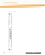
Страница 64: ...Controls LEDs and Connectors ATCA F120 Installation and Use 6806800D06F 64 Figure 3 2 Face Plate ...
Страница 73: ...Controls LEDs and Connectors ATCA F120 Installation and Use 6806800D06F 73 Figure 3 7 Face Plate LEDs ...
Страница 120: ...U Boot Firmware ATCA F120 Installation and Use 6806800D06F 120 ...
Страница 124: ...Index ATCA F120 Installation and Use 6806800D06F 124 ...
Страница 125: ......


