Functional Description
ATCA-F120 Installation and Use (6806800D06F
)
90
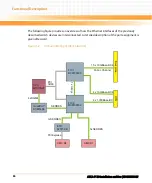
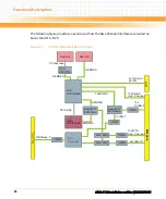
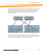
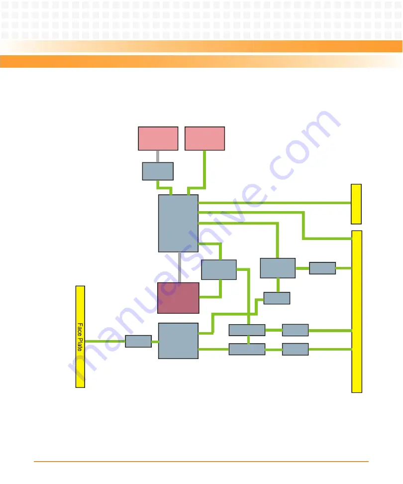
The following figure provides an overview of how the Base Channel interfaces are routed on-
board the ATCA-F120.
Figure 4-3
On-Board Routing of Base Interfaces
B
a
c
k
p
la
n
e
B
a
c
k
p
la
n
e
BIX
BMC56502
BIX
Extender
CPU
MPC8548E
PCI 32/66
QuadPHY
BCM5466
1000Base-T
RT
M
4xRGMII
SERDES
4x1000-BX
2x10G
AMC B4
AMC B1
ETH
82571EB
SERDES
SERDES
PCIExpress
XFMR
XFMR
XFMR
XFMR
XFMR
XFMR
MAX 4891
MAX 4891
2x100B-TX
100B-TX
Upd. Channel
1000B-BX
Upd. Channel
QuadPHY
BCM5466
XFMR
XFMR
16xSGMII
1000B-T
XFMR
XFMR
15x
1000B-T
Содержание ATCA-F120
Страница 6: ...ATCA F120 Installation and Use 6806800D06F Contents 6 Contents Contents ...
Страница 8: ...ATCA F120 Installation and Use 6806800D06F 8 List of Tables ...
Страница 10: ...ATCA F120 Installation and Use 6806800D06F 10 List of Figures ...
Страница 18: ...ATCA F120 Installation and Use 6806800D06F About this Manual 18 About this Manual ...
Страница 24: ...ATCA F120 Installation and Use 6806800D06F Safety Notes 24 ...
Страница 34: ...Introduction ATCA F120 Installation and Use 6806800D06F 34 Figure 1 1 Declaration of Conformity ...
Страница 64: ...Controls LEDs and Connectors ATCA F120 Installation and Use 6806800D06F 64 Figure 3 2 Face Plate ...
Страница 73: ...Controls LEDs and Connectors ATCA F120 Installation and Use 6806800D06F 73 Figure 3 7 Face Plate LEDs ...
Страница 120: ...U Boot Firmware ATCA F120 Installation and Use 6806800D06F 120 ...
Страница 124: ...Index ATCA F120 Installation and Use 6806800D06F 124 ...
Страница 125: ......

