Hardware Preparation and Installation
ATCA-F120 Installation and Use (6806800D06F
)
48
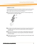
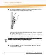
5. Fully insert the blade and lock it to the shelf by squeezing the lever and the latch
together and turning the handles towards the face plate.
If your shelf is powered, as soon as the blade is connected to the backplane power
pins, the blue LED is illuminated.
When the blade is completely installed, the blue LED starts to blink. This indicates
that the blade announces its presence to the shelf management controller.
6. Wait until the blue LED is switched off, then tighten the face plate screws which
secure the blade to the shelf.
If an RTM is connected to the front blade, make sure that the handles of both the RTM and the
front blade are closed in order to power up the blade`s payload.
Содержание ATCA-F120
Страница 6: ...ATCA F120 Installation and Use 6806800D06F Contents 6 Contents Contents ...
Страница 8: ...ATCA F120 Installation and Use 6806800D06F 8 List of Tables ...
Страница 10: ...ATCA F120 Installation and Use 6806800D06F 10 List of Figures ...
Страница 18: ...ATCA F120 Installation and Use 6806800D06F About this Manual 18 About this Manual ...
Страница 24: ...ATCA F120 Installation and Use 6806800D06F Safety Notes 24 ...
Страница 34: ...Introduction ATCA F120 Installation and Use 6806800D06F 34 Figure 1 1 Declaration of Conformity ...
Страница 64: ...Controls LEDs and Connectors ATCA F120 Installation and Use 6806800D06F 64 Figure 3 2 Face Plate ...
Страница 73: ...Controls LEDs and Connectors ATCA F120 Installation and Use 6806800D06F 73 Figure 3 7 Face Plate LEDs ...
Страница 120: ...U Boot Firmware ATCA F120 Installation and Use 6806800D06F 120 ...
Страница 124: ...Index ATCA F120 Installation and Use 6806800D06F 124 ...
Страница 125: ......

