Hardware Preparation and Installation
ATCA-F120 Installation and Use (6806800D06F
)
44
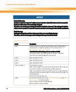
Blade Malfunction
Switches marked as 'reserved' might carry production-related functions and can cause the
blade to malfunction if their setting is changed.
Therefore, do not change settings of switches marked as 'reserved'. The setting of switches
which are not marked as 'reserved' has to be checked and changed before blade installation.
Blade Damage
Setting/resetting the switches during operation can cause blade damage.
Therefore, check and change switch settings before you install the blade.
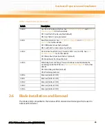
Table 2-4 Switch Settings
Switch
Description
SW1-1
Selects whether the shelf manager (ShM) is accessed through Base
Channel port 1 or Update channel port 0. For details refer to
.
Note that this switch setting can be overwritten via IPMI.
OFF: ShM is accessed through Update Channel port 0 (default)
ON: ShM is accessed through Base Channel port 1
SW1-2
Reserved (default: OFF)
SW1-3
Reserved (default: OFF)
SW1-4
Reserved (default: OFF)
SW2-1 and SW2-2
Serial interface routing
SW2-1 OFF and SW2-2 OFF (default): Serial interface of CPU is routed to
the F120 face blade and serial interface at RTM is disabled
SW2-1 ON and SW2-2 OFF: serial interface of CPU is routed to theRTM’s
face plate and serial interface of IPMC is routed to the F120 face plate (for
debugging only)
Other switch settings: Reserved
SW2-3
User flash #1 write protection. See
and
for further details.
OFF: User flash #1 write-enabled (default)
ON: User flash #2 write-protected
Содержание ATCA-F120
Страница 6: ...ATCA F120 Installation and Use 6806800D06F Contents 6 Contents Contents ...
Страница 8: ...ATCA F120 Installation and Use 6806800D06F 8 List of Tables ...
Страница 10: ...ATCA F120 Installation and Use 6806800D06F 10 List of Figures ...
Страница 18: ...ATCA F120 Installation and Use 6806800D06F About this Manual 18 About this Manual ...
Страница 24: ...ATCA F120 Installation and Use 6806800D06F Safety Notes 24 ...
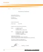
Страница 34: ...Introduction ATCA F120 Installation and Use 6806800D06F 34 Figure 1 1 Declaration of Conformity ...
Страница 64: ...Controls LEDs and Connectors ATCA F120 Installation and Use 6806800D06F 64 Figure 3 2 Face Plate ...
Страница 73: ...Controls LEDs and Connectors ATCA F120 Installation and Use 6806800D06F 73 Figure 3 7 Face Plate LEDs ...
Страница 120: ...U Boot Firmware ATCA F120 Installation and Use 6806800D06F 120 ...
Страница 124: ...Index ATCA F120 Installation and Use 6806800D06F 124 ...
Страница 125: ......

