U-Boot Firmware
ATCA-F120 Installation and Use (6806800D06F
)
112
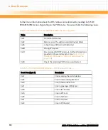
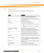
Furthermore, information about the POST status can be obtained by reading the SYS FW
PROGRESS IPMI sensor. Depending on the POST status, this sensor holds the following values.
Table 5-4 Post Results in SYS FW PROGRESS IPMI Sensor Reading Data
Value
Description
0x01
No memory detected
0x02
Memory error. The address and data line test failed.
0x0b
U-boot image CRC mismatch detected
0x0D
Wrong CPU speed.
0xfd
Emerson specific POST error code. Further information is
provided in the event data byte 3 (see
PROGRESS IPMI Sensor - POST Error Event Codes" on
page 112
)
0x00
One of the remaining POST errors was detected.
Table 5-5 SYS FW PROGRESS IPMI Sensor - POST Error Event Codes
Event Data (Byte 3)
Description
0x1E
Error accessing the switch devices
0x03
Error in network loop back test
0x20
Error in network PHY test
0x1F
Error in glue logic (FPGA) test
0x0A
Error in I2C bus test
0x16
Error in RTC test
0x09
Error in flash test
0x21
Error in CPU test
0x22
Error in PCI bus test
Содержание ATCA-F120
Страница 6: ...ATCA F120 Installation and Use 6806800D06F Contents 6 Contents Contents ...
Страница 8: ...ATCA F120 Installation and Use 6806800D06F 8 List of Tables ...
Страница 10: ...ATCA F120 Installation and Use 6806800D06F 10 List of Figures ...
Страница 18: ...ATCA F120 Installation and Use 6806800D06F About this Manual 18 About this Manual ...
Страница 24: ...ATCA F120 Installation and Use 6806800D06F Safety Notes 24 ...
Страница 34: ...Introduction ATCA F120 Installation and Use 6806800D06F 34 Figure 1 1 Declaration of Conformity ...
Страница 64: ...Controls LEDs and Connectors ATCA F120 Installation and Use 6806800D06F 64 Figure 3 2 Face Plate ...
Страница 73: ...Controls LEDs and Connectors ATCA F120 Installation and Use 6806800D06F 73 Figure 3 7 Face Plate LEDs ...
Страница 120: ...U Boot Firmware ATCA F120 Installation and Use 6806800D06F 120 ...
Страница 124: ...Index ATCA F120 Installation and Use 6806800D06F 124 ...
Страница 125: ......

