Hardware Preparation and Installation
ATCA-F120 Installation and Use (6806800D06F)
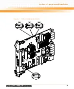
57
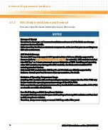
Installation Procedure
The following describes how to install an AMC module into AMC bay B1 and B4. The installation
procedure assumes that the AMC module is being hot-inserted, that means the ATCA-F120 is
powered. The procedure for the cold insertion, that means the ATCA-F120 is not powered, is
the same, except that you need not wait for the blue LED indications to proceed.
1. Make sure you are in an ESD-safe environment.
2. Identify the AMC bay to be used for the installation.
3. If the required AMC bay is occupied by an AMC filler panel, you will need to remove
the filler panel before proceeding with the installation procedure. The removal
procedure for the filler panel is the same as described in the Removal procedure
which follows immediately after this procedure. Ignore steps that mention the blue
LED.
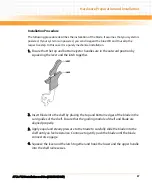
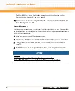
4. Ensure that the AMC module handle is in the extracted position: pulled outward,
away from the face plate.
5. Using your thumb, apply equal and steady pressure on the face plate as necessary
to carefully slide the AMC module into the guides rails.
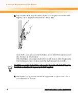
6. Continue to gently push the module along the guide rails till the module is fully
engaged with the connector.
Avoid using excessive force during this operation.
7. Wait for the blue LED to glow.
The blue LED glows when the AMC module is completely engaged with the
connector.
8. Press module handle inwards towards the face plate to lock the AMC module on
AMC bay.
9. Wait for the blue LED to perform a series of long blinks.
Содержание ATCA-F120
Страница 6: ...ATCA F120 Installation and Use 6806800D06F Contents 6 Contents Contents ...
Страница 8: ...ATCA F120 Installation and Use 6806800D06F 8 List of Tables ...
Страница 10: ...ATCA F120 Installation and Use 6806800D06F 10 List of Figures ...
Страница 18: ...ATCA F120 Installation and Use 6806800D06F About this Manual 18 About this Manual ...
Страница 24: ...ATCA F120 Installation and Use 6806800D06F Safety Notes 24 ...
Страница 34: ...Introduction ATCA F120 Installation and Use 6806800D06F 34 Figure 1 1 Declaration of Conformity ...
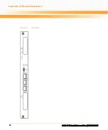
Страница 64: ...Controls LEDs and Connectors ATCA F120 Installation and Use 6806800D06F 64 Figure 3 2 Face Plate ...
Страница 73: ...Controls LEDs and Connectors ATCA F120 Installation and Use 6806800D06F 73 Figure 3 7 Face Plate LEDs ...
Страница 120: ...U Boot Firmware ATCA F120 Installation and Use 6806800D06F 120 ...
Страница 124: ...Index ATCA F120 Installation and Use 6806800D06F 124 ...
Страница 125: ......

