U-Boot Firmware
ATCA-F120 Installation and Use (6806800D06F)
107
Use the environment variable
mtdroot
to select the Linux device (NAND flash) which holds
the desired root file system. By default, the device is
/dev/mtdblock:
, i.e. by default the
root file system in NAND flash #1 is used. The device corresponding to the NAND flash #2 is
called
/dev/mtdblock;.
5.5
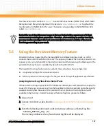
Using the Persistent Memory Feature
Persistent memory means that the memory RAM is not deleted during a reset, i.e. it still
contains the content it had before the reset. The only way to delete the memory content is via
a power cycle, i.e. by temporarily removing the power and then power up the blade again. The
persistent memory feature is enabled by default on the ATCA-F120.
The persistent memory feature can be useful in many situations. Two examples are:
z
Analyze kernel logs after a Linux kernel panic
z
Define a particular memory region for the persistent storage of application specific data
Analyzing Kernel Log Files after a Kernel Panic
If the Linux OS running on your ATCA-F120 indicates a kernel panic and you wish to analyze the
cause of it, then you can issue a reset (via the face plate button for example) and subsequently
analyze kernel log files. Because of the persistent memory feature, these log files are still
available in the memory. In order to analyze the kernel log files, proceed as follows.
1. Issue a reset
2. Connect to U-Boot as described in
Accessing U-Boot via the Serial Console
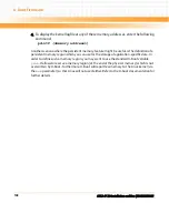
3. Enter the following command to obtain memory addresses of kernel log files
.locate_kernel_log (1)
The memory addresses of any found kernel log files will be displayed.
Each of the two U-Boot firmware images in the two flashes holds a separate set of U-Boot
environmental variables/boot parameters. Therefore, after switching to another boot flash,
you may need to reconfigure the boot parameters/environmental variables of the new U-
Boot image according to your needs.
Содержание ATCA-F120
Страница 6: ...ATCA F120 Installation and Use 6806800D06F Contents 6 Contents Contents ...
Страница 8: ...ATCA F120 Installation and Use 6806800D06F 8 List of Tables ...
Страница 10: ...ATCA F120 Installation and Use 6806800D06F 10 List of Figures ...
Страница 18: ...ATCA F120 Installation and Use 6806800D06F About this Manual 18 About this Manual ...
Страница 24: ...ATCA F120 Installation and Use 6806800D06F Safety Notes 24 ...
Страница 34: ...Introduction ATCA F120 Installation and Use 6806800D06F 34 Figure 1 1 Declaration of Conformity ...
Страница 64: ...Controls LEDs and Connectors ATCA F120 Installation and Use 6806800D06F 64 Figure 3 2 Face Plate ...
Страница 73: ...Controls LEDs and Connectors ATCA F120 Installation and Use 6806800D06F 73 Figure 3 7 Face Plate LEDs ...
Страница 120: ...U Boot Firmware ATCA F120 Installation and Use 6806800D06F 120 ...
Страница 124: ...Index ATCA F120 Installation and Use 6806800D06F 124 ...
Страница 125: ......

