U-Boot Firmware
ATCA-F120 Installation and Use (6806800D06F)
117
5.11 Updating U-Boot
Procedure
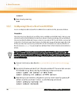
This procedure describes how you can update U-Boot via the U-Boot command line interface.
It is assumed that the new U-Boot image is placed in the download directory of a TFTP server
which has network access to the ATCA-F120. All shown files names and IP addresses were only
chosen for illustration purposes. The described procedure consists of updating the stand-by
boot flash and then switching the boot flashes, so that after the next reset/boot flash the ATCA-
F120 boots from the new active, previously updated boot flash.
1. Connect to U-boot as described in
Accessing U-Boot via the Serial Console
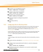
2. Specify the IP address of the ATCA-F120 itself and of the TFTP server which contains
the U-boot image by entering the following U-Boot commands:
setenv ipaddr <IP address of ATCA-F120>
setenv serverip <IP address of TFTP server>
3. Depending on your network configuration, you may have to specify a gateway IP
address as well as a netmask. To do so, use the following commands:
setenv gatewyip <gateway IP>
setenv netmask <netmask>
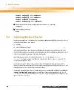
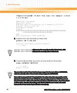
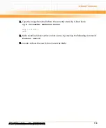
4. Load the image to the RAM.
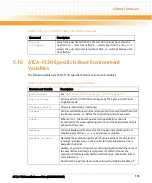
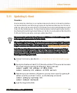
We recommend to update the U-boot firmware via BBS/Linux or via the shelf manager. Refer
to the respective documentation for further details.
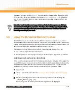
When updating the U-Boot image, the U-Boot boot parameters are not updated. They remain
as they were before the update. The boot parameters are stored separately from the U-Boot
image in a memory area within each boot flash. See also
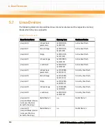
Table "Linux Devices" on page 110
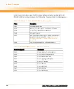
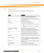
Each of the two U-Boot firmware images in the two flashes holds a separate set of U-Boot
environmental variables/boot parameters. Therefore, after switching to another boot flash,
you may need to reconfigure the boot parameters/environmental variables of the new U-
Boot image according to your needs.
Содержание ATCA-F120
Страница 6: ...ATCA F120 Installation and Use 6806800D06F Contents 6 Contents Contents ...
Страница 8: ...ATCA F120 Installation and Use 6806800D06F 8 List of Tables ...
Страница 10: ...ATCA F120 Installation and Use 6806800D06F 10 List of Figures ...
Страница 18: ...ATCA F120 Installation and Use 6806800D06F About this Manual 18 About this Manual ...
Страница 24: ...ATCA F120 Installation and Use 6806800D06F Safety Notes 24 ...
Страница 34: ...Introduction ATCA F120 Installation and Use 6806800D06F 34 Figure 1 1 Declaration of Conformity ...
Страница 64: ...Controls LEDs and Connectors ATCA F120 Installation and Use 6806800D06F 64 Figure 3 2 Face Plate ...
Страница 73: ...Controls LEDs and Connectors ATCA F120 Installation and Use 6806800D06F 73 Figure 3 7 Face Plate LEDs ...
Страница 120: ...U Boot Firmware ATCA F120 Installation and Use 6806800D06F 120 ...
Страница 124: ...Index ATCA F120 Installation and Use 6806800D06F 124 ...
Страница 125: ......


