Hardware Preparation and Installation
ATCA-F120 Installation and Use (6806800D06F
)
42
2.4
Installing Rear Transition Modules
As of writing this guide, the following rear transition module (RTM) were available: RTM-ATCA-
F120C and RTM-ATCA-F120-OPT
2.5
Configuring the Blade
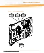
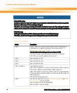
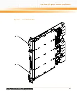
The blade provides the configuration switches SW1, SW2, SW3 and SW4. Their location is
shown in the following figure. The switch settings shown in the figure correspond to the
default settings. The switches are displayed as the small white squares.
The RTMs are not hot-swappable. Before you install them, you must make sure that either no
front blade is installed in the respective slot, or that the front blade is powered-down. For
further details about the RTM installation refer to the Installation and Use guide of the
respective RTM.
Содержание ATCA-F120
Страница 6: ...ATCA F120 Installation and Use 6806800D06F Contents 6 Contents Contents ...
Страница 8: ...ATCA F120 Installation and Use 6806800D06F 8 List of Tables ...
Страница 10: ...ATCA F120 Installation and Use 6806800D06F 10 List of Figures ...
Страница 18: ...ATCA F120 Installation and Use 6806800D06F About this Manual 18 About this Manual ...
Страница 24: ...ATCA F120 Installation and Use 6806800D06F Safety Notes 24 ...
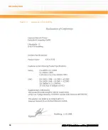
Страница 34: ...Introduction ATCA F120 Installation and Use 6806800D06F 34 Figure 1 1 Declaration of Conformity ...
Страница 64: ...Controls LEDs and Connectors ATCA F120 Installation and Use 6806800D06F 64 Figure 3 2 Face Plate ...
Страница 73: ...Controls LEDs and Connectors ATCA F120 Installation and Use 6806800D06F 73 Figure 3 7 Face Plate LEDs ...
Страница 120: ...U Boot Firmware ATCA F120 Installation and Use 6806800D06F 120 ...
Страница 124: ...Index ATCA F120 Installation and Use 6806800D06F 124 ...
Страница 125: ......

