background image

17

User Manual 

MN032EN

Effective October 2017

215U-2 802.11 

wireless I/O and gateway 


EATON

 www.eaton.com

Comm Fail Registere:

 You can choose a separate register in the 

local register map to indicate that the remote device has failed to 

respond inside the configured response timeout. If this register is a 

bit register, it will be set ON if the transaction fails, and OFF if the 

transaction is successful. If this register is a word register, it will 

receive an extended code indicating the reason for the failure. It will 

be set to zero on successful transaction. Refer to section “Modbus 

Error Codes” on 

page 51

.

Dashboard

The 215U-2 provides a dashboard feature that allows you configure 

the device so that users can view the status of the device’s local 

I/O and registers. Any authorized user can access the device’s 

dashboard remotely using a standard web browser. You configure 

which registers will be displayed on the dashboard, and how they 

will be displayed. The dashboard provides a live status of I/O, with 

regular automatic refresh.

Figure 25. Modbus client mappings

To access the dashboard, use a web-browser to browse to the 

device’s IP address. You can view the dashboard from the "Unit 

Information" section of the menu. You can also configure the 

dashboard to automatically display. The dashboard display updates 

automatically.

otee:

N

Note: Before you can access the Dashboard remotely, you need to 

enable Remote Configuration Access on the Quick Start Page.

To Configure the dashboard display, select the “Dashboard” 

item from the right side menu under “Configuration”. (Click “Full 

Configuration” under Advanced if needed).

Save Changese:

 Clicking this button saves changes to non-volatile 

storage. It also applies most of the changes you have made to the 

dashboard configuration. If you plan to make changes to multiple 

pages, use this button before navigating to another page.

otee:

N

You can quickly edit the dashboard settings and use the “Save 

Changes” button to check the result without needing to wait for the device 

to restart. Changes to the Display Color and changes to the Home Page links 

don’t take effect until you click “Save Changes and Reset” below.

Save Change and Resete:

 Clicking this button immediately applies 

the changes on you have made by saving the new configuration to 

non-volatile storage, then forcing the device to reset immediately. 

Once the device has booted, the new changes will be in effect.

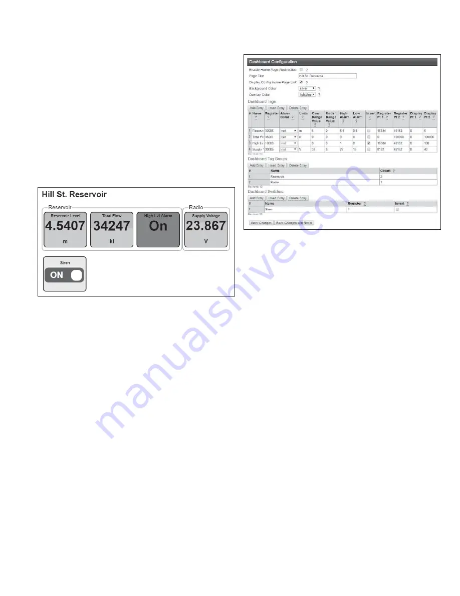
Figure 26. Dashboard configuration

Enable Home Page Redirectione:

 Check this box if you want the 

dashboard to display as soon as the user accesses the device 

webpage. This simplifies access to the dashboard for users that are 

unfamiliar with the product. If you don’t check this box, then you can 

still access the dashboard from the device menu. See "Enable Home 

Page Redirection".

Page Titlee:

 This is the title for the dashboard page. Choose 

something descriptive that identifies the site clearly.

Display Config Home Page Linke:

 If this is selected ,the dashboard 

view provides a link labelled “Configuration”. This provides a link to 

the device’s regular home page. If you don’t want your users to have 

easy access to the device’s home page, then un-check this button.

otee:

N

You can still access the home page by typing in full address to your 

browser bar: http://<Device_IPAddress>/operator/main.asp.

Background Colore:

 select a background color for your display 

panels.

Overlay Colore:

 Select a color for the overlay on your display panels 

(This shows the bar-graph level for analog values)

Dashboard Tagse:

 This section adds the panels to the dashboard that 

display the I/O status. Each row of the table describes one panel. 

Use the “Add Entry”, “Insert Entry” and “Delete Entry” buttons to 

build your list of items to display on the dashboard. For each item, 

enter the configuration parameters.

Name

The name you want to display on the individual 

panel

Register

The I/O Register that you want to have the value 

displayed

Alarm Color

The color you want the panel to change to when 

it is in the Alarm state

Over/Under  

Range Value

These settings are used for analog values. The 

analog bar displays between these two vales. 

When the scaled value goes over or under the 

corresponding limit, the panel shows “OVR” 

or “UND” rather than the measured value. To 

disable this feature, set these values to outside 

the expected range of values for the register.

Содержание 215U-2

Страница 1: ...User Manual MN032EN Effective October 2017 New information 215U 2 802 11 wireless I O and gateway Version 2 11...

Страница 2: ...r installation If this equipment does cause harmful interference to radio or television reception which can be determined by turning the equipment off and on the user is encouraged to try to correct t...

Страница 3: ...her publications pertaining to the work to be performed before installing operating or servicing this equipment Practice all plant and safety instructions and precautions Failure to follow the instruc...

Страница 4: ...tion 16 Dashboard 17 I O Mapping configuration 18 Default Back To Back gather scatter mapping 20 Serial functionality Connecting 21 to RS 232 and RS 485 device Adding expansion I O modules 22 Configur...

Страница 5: ...red to as sensitivity The default sensitivity is 1000 counts 3 but you can change this value using the device s sensitivity block configuration web page In addition to COS messages update messages are...

Страница 6: ...nfigured at a predetermined time for integrity checks Each message can be comprised of multiple I O values referred to as a block of I O The messages use error checking and return acknowledgment for g...

Страница 7: ...he main supply is present the battery will charge at up to 0 5 A rate until the battery voltage reaches 14 3 V The battery charger will then maintain a float charge on the battery at this voltage To f...

Страница 8: ...gured for each of these supply voltages See Analog inputs on page 9 for details on how to configure these alarms Grounding To provide maximum surge and lightning protection each module should be effec...

Страница 9: ...inting in the forward direction If the Yagi antenna is transmitting to a vertically mounted omni directional antenna the Yagi elements should be vertical If the Yagi is transmitting to another Yagi th...

Страница 10: ...pports Modbus protocol The RS 232 port is accessed using an RJ 45 connector wired as a DCE according to the EIA 562 Electrical Standard Table 7 RJ 45 connector RJ 45 Signal Required Signal name Connec...

Страница 11: ...ploading logged data files For details see To perform a full firmware upgrade using USB flash drive on page 53 Also see Data logging on page 38 DIP switches The DIP switches are used to select a numbe...

Страница 12: ...ency is 50 kHz for input 1 and 2 and 1 kHz for input 3 and 4 Digital pulsed inputs are suitable for TTL signal level NPN transistor switch devices or voltage free contacts a relay or switch with debou...

Страница 13: ...o floating differential analog inputs and two grounded single ended analog inputs Analog inputs 1 and 2 will automatically measure current 0 20 mA or voltage 0 25 V depending on what is connected to t...

Страница 14: ...ended current inputs Single ended current input mode is useful if the sensor loop is grounded to the 215U 2 module Devices can be powered from the 24 V analog loop supply ALS generated internally fro...

Страница 15: ...message every 10 minutes and it has not received a message within this time some form of failure is likely If the output is controlling machinery it is good design to switch off the equipment until co...

Страница 16: ...nto the browser bar The device s USB address is always the same The module responds with a username and password box 6 Type the username and password The default username is user and the default passw...

Страница 17: ...hanged Quick start configuration Access the quick start configuration by clicking on the Quick Start text on the right side menu under Configuration Figure 22 Quick start For the majority of installat...

Страница 18: ...s is the name of the repeater station that is used to reach the base station Radio Encryption Select the desired Encryption mode Normally this should be WPA2 PSK AES which is the strongest encryption...

Страница 19: ...nual Mode Client Set the System Address ESSID field to match the SSID of the Access Point For a ProMesh Mesh Node set the System Name field to match the SSID of the Access Point For a Fixed Mesh Repea...

Страница 20: ...0 and 255 Set this if your Modbus Master software requires a device ID other than 0 or 255 Enable Modbus TCP Client Select this option to enable the device to act as a Modbus TCP Client Master All Mo...

Страница 21: ...ges to the Home Page links don t take effect until you click Save Changes and Reset below Save Change and Reset Clicking this button immediately applies the changes on you have made by saving the new...

Страница 22: ...face If the device you are mapping to is not on the same subnetwork you may need to configure additional routing rules in your network to allow the message to reach its destination The 215U 2 supports...

Страница 23: ...ent this register is set back to zero Note N Don t use a Discrete input register 10001 10008 as a force register The Discrete input will not turn off and the mapping will continue to be forced while t...

Страница 24: ...he inputs units Volts mA or Hz depending on the input type I O Mapping Global Configuration allows you to configure advanced functions of the I O mappings The default values are usually suitable and w...

Страница 25: ...Set the serial data format Select from the drop down options in the format data bits parity stop bits The options support 7 or 8 data bits odd O even E mark M or space S parity and one 1 or two 2 stop...

Страница 26: ...ximum Connections If the Slave address is above the Maximum Connections it will not be polled When you connect the serial expansion module before powering on set the expansion module address using the...

Страница 27: ...ilure This value should be outside the normal range of values for the data that is setting the output Configuring the Digital Outputs You can configure the digital outputs to set up a local fail safe...

Страница 28: ...in the I O Configuration screens Fail Safe Blocks You use this configuration to set up the behavior of blocks of registers that you want to intialise to a certain status or if you want to have them g...

Страница 29: ...r country Channel You can select a radio channel to avoid interference from other 802 11 networks in your area or to allocate radio spectrum between several of your own networks For 802 11 communicati...

Страница 30: ...lowing Name Create a descriptive name for the rule to remind you of the purpose of this rule at a later date Destination This is the destination network IP address Combined with the Netmask in the fol...

Страница 31: ...u want to access the network with a device such as tablet or PC to connect to the devices in the network at their fixed network addresses Note N You must ensure there is only one DHCP server on your l...

Страница 32: ...hich would otherwise allow packets to circulate continuously on the network Interface Membership for VLAN This allows you to set which interfaces are part of the VLAN The 215U 2 has two interfaces whi...

Страница 33: ...Firmware upgrade Setting the date and time This feature is associated with data logging The module needs access to the current date and time to make effective use of data logging if this feature is e...

Страница 34: ...hour minute and second and click Pick again to set the time and close the pop up To set the time more precisely try selecting a time a little in the future and waiting until that time to click Pick S...

Страница 35: ...key on this page Using demonstration mode The demonstration mode option on the Feature License Keys page Figure 40 temporarily allows full operation of all feature license options for 16 hours or unt...

Страница 36: ...s Operator Can view information on the device but cannot change configuration Manager Can view information and change the device configuration but cannot modify the list of users allowed to access the...

Страница 37: ...er Management on the menu 2 In the Status column for the user click Retire 3 Click OK to confirm The user s status changes from Active to Retired 4 Click Save and Activate Changes This disables access...

Страница 38: ...er address location Count Number of consecutive registers starting from the register location specified in the Register field Value Value to be written Read To read a register location enter an addres...

Страница 39: ...Analog Input Registers These are listed in detail in Input registers on page 45 Statistics registers provide the following information about the upstream connection Towards the base station If the mod...

Страница 40: ...register locations For each downstream device the last byte of the device s IP address is used to determine which location to store the signal strength For example a downstream device with IP Address...

Страница 41: ...need Administrator or Manager privileges to configure data and event logging Figure 45 Data and event logging configuration Data log configuration The configuration example in see Figure 47 will log...

Страница 42: ...ome page of the Web based configuration utility The latest data is shown in a csv format on the screen Figure 47 Log information Retrieving logged data The module supports remote retrieval of files vi...

Страница 43: ...transferred and the OK LED turns green Figure 49 USB port 5 Remove the USB drive from the module USB port The log files are contained in a directory under the logs directory This subdirectory is named...

Страница 44: ...00 230400 bps Serial Settings 7 8 Data Bits Stop Start Parity Configurable Protocols and Configuration Protocols Supported TCP IP UDP HTTP FTP TFTP Telnet Modbus RTU Master Slave Modbus TCP Client Ser...

Страница 45: ...u can plug the USB cable back in to access the device using the default credentials Important Remember to set DIP switch 6 to off and power cycle the module to return to normal operation after you hav...

Страница 46: ...search box At the command prompt type ping 192 168 111 1 LED function Front panel LEDs When the module is initially connected to power it performs internal setup and diagnostics checks to determine if...

Страница 47: ...LED is mostly on long on it indicates that the fail safe state shown on the Digital Output Configuration page is on If an LED is mostly off long off it indicates that the fail safe state shown on the...

Страница 48: ...30013 30016 Local pulse input rates PI1 PI4 30018 30020 Spare 30021 30400 Space for locally attached 115s expansion I O modules Twenty registers per module address maximum number of modules is 19 3040...

Страница 49: ...orresponding register has the value Zero 32256 36000 General purpose word storage used for Staging area for data concentrator Fieldbus mappings storage 36001 36008 Local pulsed inputs 1 4 big endian f...

Страница 50: ...3 would be 3x20 30003 30063 Analog output 8 on an 115S 13 with address 7 would be 7x20 40007 40147 I O store for 115S 11 expansion I O modules I O store Description 0001 Offset 0016 Offset DIO output...

Страница 51: ...fset 10008 Offset DIO inputs 1 8 10019 Offset Modbus Error indication for 115S module 10020 Offset Detected indication for this 115S module 30017 Offset Modbus Error counter for this 115S module 30018...

Страница 52: ...lsed Output 1 Count 46001 46002 Pulsed Output 2 Count 46003 46004 Pulsed Output 3 Count 46005 46006 Pulsed Output 4 Count 46007 46008 Analog Input 1 Floating Point mA 38001 38002 Analog Input 2 Floati...

Страница 53: ...log I O 5 30005 40005 Analog I O 6 30006 40006 Analog I O 7 30007 40007 Analog I O 8 30008 40008 Pulsed I O Count 1 30017 30018 30009 30009 30009 Pulsed I O Count 2 30019 30020 30010 30010 30010 Pulse...

Страница 54: ...r has a value outside the expectation of the application program The Modbus protocol is unaware of the significance of any particular value of any particular register 65384 FF04 Slave Device Failure A...

Страница 55: ...ECTING THE WRONG DRIVE COULD FORMAT YOUR PC S HARD DRIVE DISKPART select Disk 1 Disk 1 is now the selected disk 5 Enter the command list partition to check how the USB drive is partitioned This comman...

Страница 56: ...ng USB flash drive 1 Connect to the module s Web based configuration utility and make a note of the current firmware version which appears on the home Web page This will enable you to compare versions...

Страница 57: ...October 2017 215U 2 802 11 wireless I O and gateway EATON www eaton com Figure 58 Firmware upgrade LED indicators 6 When the upgrade is complete remove the USB flash drive from the module s USB port a...

Страница 58: ...rogram or a portion of it either verbatim or with modifications and or translated into another language Hereinafter translation is included without limitation in the term modification Each licensee is...

Страница 59: ...ecipients exercise of the rights granted herein You are not responsible for enforcing compliance by third parties to this License 7 If as a consequence of a court judgment or allegation of patent infr...

Страница 60: ...Y AND PERFORMANCE OF THE PROGRAM IS WITH YOU SHOULD THE PROGRAM PROVE DEFECTIVE YOU ASSUME THE COST OF ALL NECESSARY SERVICING REPAIR OR CORRECTION 12 IN NO EVENT UNLESS REQUIRED BY APPLICABLE LAW OR...

Страница 61: ...crypts outgoing wireless data On the receiving side the same encryption key enables the computer to automatically decrypt the information so it can be read Encryption keys should be kept secret EIRP E...

Страница 62: ...that provides its resources to other computers and devices on a network These include print servers Internet servers and data servers A server can also be combined with a hub or router SMA SMA SubMini...

Страница 63: ...veland OH 44122 United States Eaton com 2017 Eaton All Rights Reserved Printed in USA Publication No MN032EN CSSC 1703 4112 October 2017 Eaton is a registered trademark All other trademarks are proper...

Отзывы: