21
User Manual
MN032EN
Effective October 2017
215U-2 802.11
wireless I/O and gateway
EATON
www.eaton.com
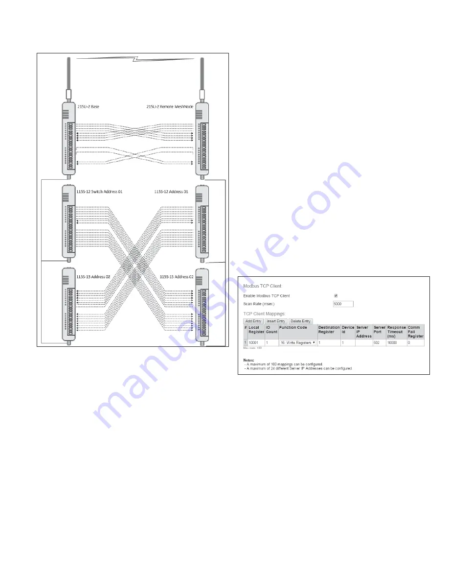
Figure 28. Back to Back mappings
Serial functionality – Connecting to RS-232 and
RS-485 devices
The 215U-2 has an RS-232 and an RS-485 port for serial
communications. You can use these ports to connect to external
devices using serial server functionality or using the in-built Modbus
client or server functionality.
From the right-side menu, select “Configuration >> Serial” to
configure the serial port operation.
You can configure the operation of the RS-232 and RS-485 serial
ports separately. By default, the RS-485 serial port is configured to
support automatic connection to 115S I/O expansion modules. The
available options for each serial port are
Port Type
. This selects the
operating mode for the port.
None
Disables all functionality on the serial port.
Expansion I/O
Allows connection to 115S Expansion I/O
modules.
Modbus RTU
Slave
Configures the port to act as a Modbus slave
to a Modbus master device connected to the
serial port.
otee:
N
Make sure that "Enable Modbus TCP Server" is
selected on the Modbus TCP page.
Serial Server
You can configure the port to act as a serial
server. In this mode, you connect to the device
on standard TCP port to access the device’s
serial port from a remote TCP connection.
Modbus RTU
Master
Configures the port to operate as a Modbus
master device. The commands are configured
in the “Modbus Master Mappings” table that is
enabled when you select this option (see below).
otee:
N
Make sure that "Enable Modbus TCP Client" is selected on the Modbus
TCP page.
Data Ratee:
Set the serial baud rate to match the connected device.
Standard baud rates from 1200 baud to 115,200 baud are supported.
Data Formate:
Set the serial data format. Select from the drop-down
options in the format <data-bits><parity><stop-bits>. The options
support 7 or 8 data bits, odd (O), even (E), mark (M) or space (S)
parity, and one (1) or two (2) stop bits.
Flow Controle:
(RS-232 port only) This allows you to enable hardware
flow control on the RS-232 port. Because Modbus is a poll-response
protocol, the flow control will normally be set to “None”. When using
the serial server, you should set this to match the settings of the
device you are connecting to.
Maximum Device ID to polle:
(only for Expansion I/O setting). This
is the maximum device ID for connected 115S modules. Set this to
match the actual number of 115S modules connected to speed up
the I/O device polling.
Modbus RTU Master settingse:
Some additional items are available
when you select this mode.
Figure 29. Modbus RTU Master settings
Scan Rate (msec)e:
This is the time delay in milliseconds between
completing the processing of one Modbus Master Mapping and
beginning the next. This delay begins after receiving a response to a
client mapping message, or if there is no response, at the end of the
timeout for that message.
Response Timeout (msec)e:
This is the time that the Modbus
master will wait for a response from the remote Modbus slave
before deciding that the transaction has failed.
Modbus Master Mappingse:
Use the “Add Entry”, “Insert Entry”
and “Delete Entry” buttons to build your list of Modbus commands.
For each command, you set the following items.
Local Register
This is the register in the local device that will
either receive the data from the remote device
(Read command) or be used as data to send to
the remote device (Write command). Refer to
section "Register Memory Map" on page 45 for
detail of the local device register map.
I/O Count
The number of I/O points to transfer. For bit (Coil)
commands, this is the number of 1-bit registers
to transfer. For register (Word) commands, this is
the number of 16-bit registers to transfer.


