22
User Manual
MN032EN
Effective October 2017
215U-2 802.11
wireless I/O and gateway
EATON
www.eaton.com
Function Code
The Modbus function code to use in the
message.
Destination
Register
The register number in the remote device that
will either be used as a destination for the
data transfer (Write) or as a source for the data
(Read).
Device ID
The Modbus Device ID (also called Device
Address) for the remote device.
Comm Fail
Register
You can choose a separate register in the local
register map to indicate that the remote device
has failed to respond inside the configured
response timeout. If this register is a bit register,
it will be set ON if the transaction fails, and OFF
if the transaction is successful. If this register is
a word register, it will receive an extended code
indicating the reason for the failure. It will be
set to zero on successful transaction. Refer to
section “Modbus Error Codes” on
page 51
.
Modbus TCP to RTU Gateway
allows an Ethernet Modbus/TCP
Client (Master) to communicate with a serial Modbus RTU Slave.
The 215U-2 performs the protocol conversion and is directly
connected to the Modbus serial device (i.e. only this module needs
to have Modbus TCP to RTU Gateway enabled).
Adding expansion I/O modules
You can connect additional 115S serial expansion I/O modules to
the 215U-2 module if more I/O is required. The RS-485 serial port
on the 215U-2 is configured by default to communicate with 115S
expansion modules using the Modbus protocol. The default serial
parameters of the RS-485 port on the 215U-2 are 9600 baud, no
parity, 8 data bits, 1 stop bit, which match the default settings of the
115S serial expansion modules. You can change these parameters
to increase poll speeds in larger systems, but the serial module’s
parameters must match that of the 215U-2 RS-485 port.
If more than three serial expansion I/O modules are added to the
215U-2 module, you will need to adjust the Maximum Connections
setting for RS-485 or RS-232.
otee:
N
Reducing the Maximum Connections setting will slightly improve the
serial scan time. However, you need to make sure that the slave addresses
fall within the Maximum Connections. If the Slave address is above the
Maximum Connections, it will not be polled.
When you connect the serial expansion module, before powering
on, set the expansion module address using the rotary switches on
the bottom of the module. Assign addresses sequentially, starting
at address 1. Make a note of the module address. This address will
be used as an offset to locate the I/O within the 215U-2. Also make
sure that the termination switch is “on” (down) for the last module in
the RS-485 loop.
otee:
N
Failure to terminate the RS-485 correctly will result in modules not
operating correctly.
115S Expansion I/O Memory Mape:
The I/O data on the 115S
module is read into memory locations according to their Modbus
address. The maximum supported Modbus address is 19. Each 115S
module has an offset that applies to the location of its registers.
This offset is equal to the units' Modbus address (selected on
the rotary switch on the end of the 115S expansion I/O module),
multiplied by 20. If the modules Modbus address is 15, the offset
value will be 15 X 20 = 300.
For example, if connecting a 115S-11 (16 x DIO) with address #15:
•
Digital input 1 will be at register location 10301
•
Digital Output 1 will be at register location 301.
•
If using a 115S-12 (8 x DIO and 8 AIN) with address 16:
•
Digital input 1 will be at register location 10321
•
Analog input 1 will be at register location 30321 For a detailed
address map of the serial expansion I/O modules, see section
“Expansion I/O Registers” on
page 47
.
When adding expansion I/O modules to the 215U-2, there are
two inbuilt registers indicating the communication status of the
expansion I/O module:
•
Communication Fail
— Located at register location 10019 +
offset value. This register indicates “1”when the module is in
failure.
•
Communication OK
— Located at register location 10020
+offset value. This register indicates “1”when the module is
communicating properly.
Configuration of the on-board I/O
The default I/O configuration on the 215U-2 module is suitable for
most applications. If needed, you can change the configuration
to meet the special needs of your application. You access the I/O
configuration through the right-side menu under “Configuration >>
Onboard I/O”.
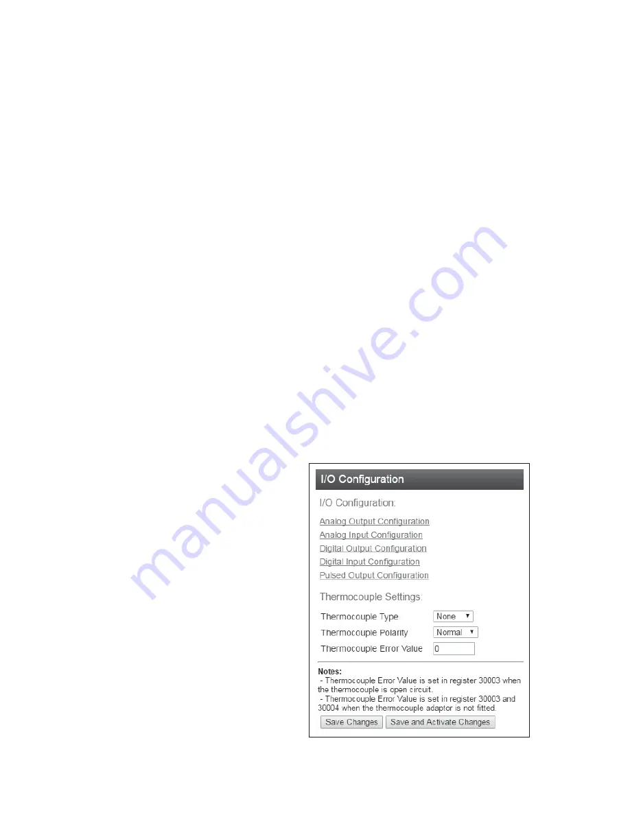
From Here, configure the thermocouple input directly, or select the
type of I/O you want to configure.
Figure 30. I/O Configuration


