


23
User Manual
MN032EN
Effective October 2017
215U-2 802.11
wireless I/O and gateway
EATON
www.eaton.com
Configuring For use with the TC-ADP thermocouple modulee:
You can purchase the Thermocopule module (TC-ADP) separately.
This replaces analog inputs 3 and 4. Look at the documentation with
the TC-ADP module for a detailed description on configuring. If you
are not using the thermocouple module, ensure Thermocouple Type
is set to “None”.
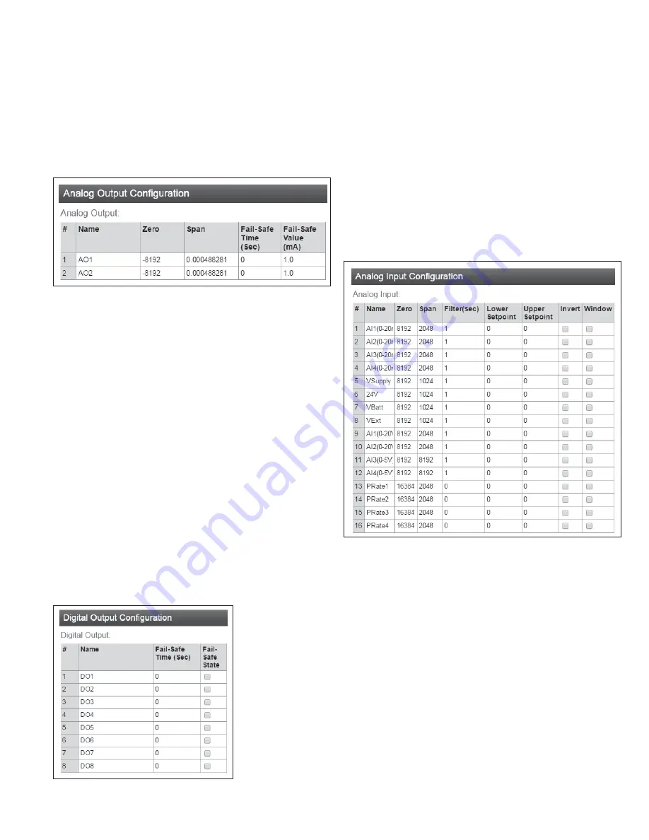
Configuring the Analog Outputse:
You can configure the analog
outputs to change the way the outputs are scaled, and to set up a
local fail-safe in the case that communications is lost.
Figure 31. Analog output configuration
Name
You can give the I/O point a descriptive name if
you like.
Zero and Span
These values set the scaling of the analog
outputs. The scaling values are applied to the
raw register value, to give the output value in
milli-amps. The raw value is a 16-bit unsigned
value. The zero value has units of raw-counts.
The Span value has units of milli-amps per
raw-count.
Output(mA) = Span × (Raw + Zero)
Fail-Safe Time
(Sec)
The output needs to receive an message
updating its status before this time expires.
Normally this is set to at least twice the
update time for the message that sets the
output status.
Fail-Safe Value
(mA)
If there is no update message received within
the configured Fail-Safe time, then the output is
set to this value to indicate the communications
failure. This value should be outside the normal
range of values for the data that is setting the
output.
Configuring the Digital Outputse:
You can configure the digital
outputs to set up a local fail-safe in the case that communications
is lost.
Figure 32. Digital output configuration
Name
You can give the I/O point a descriptive name if
you like.
Fail-Safe Time
(Sec)
The output needs to receive a message updating
its status before this time expires. Normally this
is set to at least twice the update time for the
message that sets the output status.
Fail-Safe State
If there is no update message received within
the configured Fail-Safe time, then the output is
set to this value to indicate the communications
failure. Check this box to have the output fail
“On”. Clear to have the output fail to “Off”.
Configuring the Analog Inputse:
You can configure the behavior of
the analog inputs to change the way the inputs are scaled, and to
configure the behavior of the digital set-points that are associated
with the analog inputs.
Figure 33. Analog input configuration
Name
You can give the I/O point a descriptive name if
you like.
Zero and Span
These values set the scaling of the analog
inputs. The scaling values are applied to the
measured value (either volts, milli-amps, or
hertz), to give the 16-bit raw register value. The
zero value has units of raw-counts. The Span
value has units of raw-counts per measured unit.
For current input
(measured value is in mA)
Raw = Zero + Span × Measured(mA)
For voltage input
(measured value is in V)
Raw = Zero + Span × Measured(V)
For pulse rate
input
(measured value is in Hz)
Raw = Zero + Span × Measured(Hz)


