background image

Y:\Arabel\UL\ELAUT_UL\TCF11158.doc  


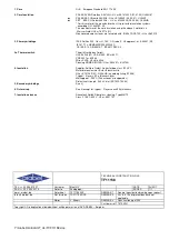
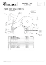
1. Core


: Hi-B    European Standard EN 117-30-P 

 
2. Core Insulation 


: PA6.6 BAYER-Durethan AKV-30H –UL nr.E41613A1A (21.01.00) UL94HB*  


or         

PA6.6


BASF-Ultramid A3X2G5 –UL nr. E135532 (06.06.01)   UL94V0 


or 

  PBT    BASF- Ultradur 4300G6 -   UL nr. E1335532 (05.05.98)  UL94HB 

 * For this material the manufacturer has UL-pre-tested insulation systems 
   according UL-1446/IEC 85. 
 The manufacturer of the core insulation using the above 3 materials is 
  Weisser GmbH UL nr.185713 (N) 
 Non covered core surfaces are insulated with :IDEAL TAPE 702 –UL nr E82910 


3. Primary windings 


: IRCE Poliflex 200  Class H, 180° C, Grade 2 - UL approval : nr. E60641 (M)  
   IEC317-13, NEMA MW1000 MW35_C 
   CEI 55-2-13, DIN46416-7,  BS6811 SEC3.3  
 

3a. Thermal switch  


: Thermik Gerätebau GmbH, 
  UL E54 236 (M), CSA 41402, BS nr.6371, 
  VDE 0631 nr. 60548 
  Wires XLPE, UL style 3266 


  Sleeving NOMEX-MYLAR (UL nr. E34739) 


4. Insulation


: Supplier :Polifibra GmbH, Polyestertape class B 130°C 


  Material manufacturer :Ester Industries Ltd. 


  UL nr. E121262 (M) - UL94-HB ( according listing 5/1998) 


  Typical : 6 layers, 50 µ thickness/layer 


  Melting point : 250°C (Fisher-Jones mp apparatus) 


  Dielectrical strength : 280 kV/mm (ASTM 0-149-64) 

5. Secundary windings


: See 3) 


6. Outer wrap 


: See 4) except for: typical : 2 layers each 50µ thickness 


7. Insulation sleeves


: Rhenatech Gmbh,Fiber glass sleeving, Type M8172 


  Class F 155°C,600 V, UL nr. E201197 


TECHNICAL CONSTRUCTION FILE 

TF11158 

TEL. ++ 32 2 569 15 27 

Customer  

Elaut NV 


DATE 

03/2011 

FAX. ++ 32 2 569 23 70 

Refer to 

Photograph : 


PAGES 

1/1 

www . arabel . be 

Datasheet 

TF11158.XLS 

REMARK 1 

General construction drawing upon request 

Info @ arabel . be 

Ref this doc. 

TCF11158.DOC 

REMARK 2 

Nrs. 8,9,10 not present because not 
applicable 


Editor 

Y. Allaert 

REMARK 3 

Construction type IP00 


Customer ref  7510.0231 

Copyright 

 No duplication allowed without written permission of NV ARABEL – Belgium. 


Содержание Big One X-treme

Страница 1: ...technical file Big One X treme 1 MANUAL 2 CABINETS 3 PRIMARY CIRCUITS 4 ELECTRONICS 5 FUNCTIONALITY 6 WIRING...

Страница 2: ...technical file Big One X treme 1 MANUAL 2 CABINETS 3 PRIMARY CIRCUITS 4 ELECTRONICS 5 FUNCTIONALITY 6 WIRING...

Страница 3: ...Building X treme Big One i Document versie V1 1 Building Guidelines X treme Big One Auteur Hoefman Dirk...

Страница 4: ...Building X treme Big One ii Document versie V1 1 History Version Release Date Remarks V1 0 12 04 2016 First Release V1 1 02 05 2016 Chapter3 4 15 18...

Страница 5: ...to put the focus on some detail Please be aware before setting up the X treme Big One that the power entrance is located below in the Console box This can be accessed through the rear of the Console b...

Страница 6: ...le box you will find more parts cables Contains the gantry Contains the prize part You will find 2 top parts of the machine Unpacking This document contains guidelines to build the big one extreme Eve...

Страница 7: ...en unpacking the frame parts you should notice that these are numbered from F1 up to F9 Please make sure that all frames are mounted correctly firmly fixed First we start to assemble F1 and F2 Each co...

Страница 8: ...following panel to be mounted is F4 using the same 5 screws F3 F4 Please be aware that the PCB s for the running RGB lights are mounted on the panel F2 F3 Do make sure these are not damaged These are...

Страница 9: ...we will install frame part F5 then part F6 and part F7 Each upper part is fixed to the lower part using screws M6x90 washer M6 nut M6 This will be done at the inner side of the frame F5 F6 F6 F7 6051...

Страница 10: ...half will be fixed with 5 screws as shown below The upper front F8 will be fixed in the corners as shown above and at the inside it will be fixed to the lower part with 2 times 2 connections 6050 066...

Страница 11: ...ig One 6 Document versie V1 1 The latest part to be mounted is frame F9 Notice the frame F9 will be installed from the outside This will be fixed with 8 screws M6x60 at the inside of the frame 6051 06...

Страница 12: ...nt At the front the head front long is equipped with a bracket containing a Power supply a RGB controller and a Domino PCB already installed cables in a cable guide The short parts are marked with L f...

Страница 13: ...he bottom rear should fit in the groove of the aluminium profile at the bottom of frame F4 Once this is at his place it can be fixed with the toggle latch The latch should be fitted into the hook whic...

Страница 14: ...rols casing should be then connected to the grounding lip of the frame F4 We will now fix the wooden floorplate labelled B6 on the door entrance as shown in picture below This plate should be equipped...

Страница 15: ...through the cable guides which are situated at the door wooden panel B6 and at the bottom of the right frame F3 and back frame F2 You ll notice that the RGB controller boards power cables have a diff...

Страница 16: ...uides up to the mid of the rear panel F2 There we ll need to cut a hole in the cable guide so the mains cable can could be guided up towards the TV powercord We will now guide the TV mains powercord t...

Страница 17: ...acables The next step is to connect all data cables 9015 1257 9015 1258 9015 1259 between the controller boards and the RGB ledstrips and installing the RGB led PCB s Below is the picture which shows...

Страница 18: ...up to RGB_4 will be guided outside to the corner of the frame through the holes foreseen We start now with the placement of the RGB led boards in each corner In the package is a bag with about 80 pie...

Страница 19: ...e of mounting the RGB led boards see marking at the back of the led boards 1x A to start with at bottom 9x B The PVC print montage parts will be placed at the beginning and end of each completed RGB l...

Страница 20: ...Building X treme Big One 15 Document versie V1 1 A B B B B B B B B B PVC print montage Completed RGB led board strip...

Страница 21: ...ures below which show how to connect the RGB led boards to each other The picture below show cable 9015 1258 datacable for upper strip When required the cables 9015 1258 datacable for upper strip and...

Страница 22: ...Building X treme Big One 17 Document versie V1 1 The pictures below show the assembly of the upper RGB led strip A B B B B B C PVC print montage...

Страница 23: ...the end of the lower strip and the beginning of the upper strip join together Once all datacables and powercables are connected the remaining length can be folded and guided into the cable guide Once...

Страница 24: ...eces with RGB leds We first connect the split cable to the upper rgb led board already present in the corner We can now lift the corner piece screw thread over the head front holes We can now fix each...

Страница 25: ...ument versie V1 1 Before fixing the 2 sides we will properly fold the present cable so it is not visible Then we fix each corner piece drill the holes first with a drill of 3 6mm and then fix it with...

Страница 26: ...casing We will now guide the following cable upwards through the cable guides o 2 loudspeakercables o Gantry cable o Mains cable These cables can be found in the compartment at the right from the door...

Страница 27: ...Building X treme Big One 22 Document versie V1 1 Now we guide the cables through the following cable guides upwards see following 3 pictures...

Страница 28: ...Building X treme Big One 23 Document versie V1 1...

Страница 29: ...eed to dismount the bracket first Each bracket will be mounted on the frame see picture below with 2 screws M6x20 6111 0620 2 washers M6 6092 0058 and 2 lock washers M6 6090 0006 At the places where t...

Страница 30: ...versie V1 1 Now we can connect the cables from the ledspots to the screwless connector which can be found on the yellow front head At the same time we can connect the mains cable coming from the contr...

Страница 31: ...nt head Each loudspeaker will be fixed with 2 screws M4x10 6030 0410 4 washers M4 6092 0042 and 4 lock washers M4 6090 0004 The cable of the loudspeaker should be guided through the hole as shown in p...

Страница 32: ...hrough the cable guide from the head front long to the other side This extension cable should be connected to the ledstrip cable which is fixed on the head front short L There is also another extensio...

Страница 33: ...Installing connecting the price casing The price casing will be shifted up to the front panel and fixed with 2 selftapping screws 6170 4213 We can now make the connection between the cable from the p...

Страница 34: ...ttom should be installed as shown below All panels will be fixed against each other to fit the frame To fix the wooden plates to each other screws M4x40 chipboard 6150 0070 shall be used To fix the pl...

Страница 35: ...m in the aluminium frame at these locations once the plate has been well positioned 100mm from the aluminium frame as shown in picture below The panels will be place in the following sequence B1 B2 B3...

Страница 36: ...V1 1 The following pictures show this sequence Panel B1 Panel B2 Chipboard screw M4x40 6150 0070 Parker screw M4 2x32 6122 0832 Drill holes of 3 6mm first Chipboard screw M4x40 6150 0070 Parker screw...

Страница 37: ...2 Document versie V1 1 Pay attention that when installing panel B2 the mains cable for the TV will be guided through the opening as shown in picture below Panel B3 fix as shown in previous pictures wi...

Страница 38: ...Building X treme Big One 33 Document versie V1 1 Panel B4 fix as shown in previous pictures with the appropriate screws...

Страница 39: ...reme Big One 34 Document versie V1 1 10 Mounting the 2 inner short cover plates head The 2 cover plates at both sides will be installed The lips from the cover plates should fit into the slots from th...

Страница 40: ...ng X treme Big One 35 Document versie V1 1 11 Mounting the 4 endstop X treme Gantry In the packaging normally in Box1 you should find 4 endstops These will be fixed in the frame with a screw M4x16 603...

Страница 41: ...Big One 36 Document versie V1 1 12 Mounting the Gantry and connect To be able to fit lift the gantry minimum 2 people are required At both sides you should notice a round rod where the wheels of the g...

Страница 42: ...rsie V1 1 This part of the gantry should be held to the left when lifting The gantry cable coming from the controls casing shall be connected to the cable coming from the gantry Then the gantry cable...

Страница 43: ...Building X treme Big One 38 Document versie V1 1 The available gantry cable should still be long enough so the gantry can reach every corner of the playfield...

Страница 44: ...Before mounting the TV we should connect the RCA cable to the camera wire as shown in picture below It can be fixed to the gantry by a couple of cable ties We should now place the cover plate at the r...

Страница 45: ...art connector to the TV at the rear and connect then the RCA cable to this connector to the output Now we can connect the mains cable which should already be available coming from below At the rear of...

Страница 46: ...V1 1 We can now lift the TV bracket on the bracket present at the rear of the frame Make sure that it fits well on the this bracket Finally we should check that the RCA cable is long enough so the gan...

Страница 47: ...lding X treme Big One 42 Document versie V1 1 14 Mounting the last cover plate We can now install the cover plate at the front The lips from the cover plates should fit into the slots from the head fr...

Страница 48: ...V1 1 15 Mounting the 3 ceiling parts Before mounting the ceiling we need to remove the protecting foil The ceiling parts will be installed with the white side downwards We start at the rear of the fra...

Страница 49: ...Building X treme Big One 44 Document versie V1 1 The ceiling will be fixed first we drill holes with a drill of 3 6mm and then we fix it with selftapping screws 6170 4213...

Страница 50: ...45 Document versie V1 1 16 Mounting the 4 corner pieces head Before mounting the corner piece head we need to remove the protecting foil In all 4 corners we will mount the corner piece head each with...

Страница 51: ...ent versie V1 1 17 Mounting the 4 Aluminium tubes on top When required for the customer the 4 aluminium tubes 25x25 can be mounted on top Therefore we will use for each tube 2 screws M4x35 6030 0435 a...

Страница 52: ...ound the pricing casing The lexan protection will be placed behind the price casing To fix it we will use 10 chipboard screws M4x16 6152 4016 to fix it to the bottom plates and selftapping screws 6170...

Страница 53: ...t versie V1 1 19 Mounting the transparent white corners At each corner there will be 2 transparent white corners installed the longest L 1900mm below and the shortest L 1333 above oPicture below shows...

Страница 54: ...Building X treme Big One 49 Document versie V1 1 20 Mounting the doorknob For transport the doorknob has been removed This needs to be mounted again All material should be present in the package...

Страница 55: ...me Big One 50 Document versie V1 1 21 Mounting the lexan 200x690 at the door entrance The lexan can be mounted at the door entrance with 4 chipboard screws 4x16 6150 0046 Remove the protecting foil be...

Страница 56: ...1 22 Finish The X treme Big One is now ready for testing and set up At the camera there are 2 settings possible Zoom and Focus The setting change can be done with a hex key which can be found in the p...

Страница 57: ...er B3 0190 0431 1 00 ST Bottom D X treme 782x689 Number B4 1575 1242 1 00 ST Monitor 42 inch led Box TV 1741 2203 1 00 ST Conn scart plug m 3xrca m Box TV 2071 6005 1 00 SET Loudspeaker set 100w Box 1...

Страница 58: ...26 2 00 ST Head front short Big One 9015 1153 1 00 ST Cable itx rgb extension 3m Box 1 9015 1257 4 00 ST Cable rgb connection 1 2m Box 1 9015 1258 4 00 ST Cable rgb connection 3m Box 1 9015 2051 1 00...

Страница 59: ...uare profile 25x25 1 00 ST Framepanel F1 1 00 ST Framepanel F2 1 00 ST Framepanel F3 1 00 ST Framepanel F4 1 00 ST Framepanel F5 1 00 ST Framepanel F6 1 00 ST Framepanel F7 1 00 ST Framepanel F8 1 00...

Страница 60: ...l English Intelligrab 02xx revxx The Big One 03xx revxx 15 11 2006 ELAUT nv sa Passtraat 223 B 9100 Sint Niklaas Belgium Tel 32 3 780 94 80 Fax 32 3 778 05 61 Website www elaut com E mail support elau...

Страница 61: ...2...

Страница 62: ...Overview menu 8 Intelligrab 8 Intelli link 8 Accounts 8 Cashboxes 9 Manual control 9 Claw settings 9 Payout information 10 Credit values 10 Coin values 10 Bill token values 11 Game settings 11 Motor s...

Страница 63: ...4...

Страница 64: ...ey want to play themselves Very important is to tune the merchandise and the machine The size of the merchandise must be adapted to the size of the machine Key 2 A player must fall under the spell of...

Страница 65: ...a money value some coin entries can be set with a different unit e g pieces After emptying the cashbox the meters can be copied and or cleared Accounts To evaluate a long term result an accounting is...

Страница 66: ...3 can you get more information about each setting Under specific circumstances are there possibility s to test the set values by pressing Test button 4 The buttons en 5 are for changing values This i...

Страница 67: ...on number and date This information is the most important for the technical department Intelli link address every playfield in an intelli network has a unique number that can be set in this menu 1 is...

Страница 68: ...with pick up power bonus till win pick up power until next win stand by with this function you can put the playfield in stand by It s impossible to insert money and on the display you see 2 bars light...

Страница 69: ...he counters This function clears also the remaining credits Credit values fixed value by enabling you can set a fixed value for each game By disabling you can choose the amount of credits insert or in...

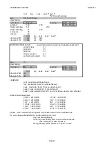
Страница 70: ...e GAME SETTINGS game time 30s 4 directions ON commande mode 0 carriage jump ON play w nudges OFF return diagonal ON stop and drop 0 smart detector ON credit limit 25 money in limit 14 0 4 directions t...

Страница 71: ...r movement ON auxiliary volume 0 volume attr volume during the attract mode sound track 1 the standard sound track 2 the optional soundtrack different in game win and attraction attr time out the inte...

Страница 72: ...me SW warn 0 i left SW warn 0 i home failure 0 i down SW stuck 0 i down SW open 0 i down failure 0 i up SW stuck 0 i up SW open 0 i up failure 0 i string broken 0 i grabber stuck 0 i grabber fail 0 S...

Страница 73: ...e motor will stop automatically finished 2 release a wrong winded up string Press T The motor will release the string and unwind the pulley so that the claw reaches the bottom Now place the string man...

Страница 74: ...pick up power keeps on After this time the pickup power turns over to retaining power You can adjust with this setting how high the merchandise may be picked up before it drops By enabling random pick...

Страница 75: ...en press S to resume Display code 4 WARNING game price to high check credit set Press S to resume The number of credits per game does not correspond with the coin value or the reference channel refers...

Страница 76: ...switching on the crane the detector becomes active Objects in the prize hole or a problem with the detector can cause this Remark the controller can t determine whether the detector works correctly WA...

Страница 77: ...to the menu mechanical diagnostics they will give you an indication of the problem so that you can solve it easily Display code 39 ERROR mechanical problem going up detected See diagnostics The system...

Страница 78: ...ON stop and drop 0 smart detector ON windoor mode 0 credit limit 25 money in limit 14 0 Motor speeds The upward and downward fastness of the motor of The Big One can be set separately even when it s...

Страница 79: ...Error Display code 43 ERROR wind door out of order press S go to SELFTEST to reposition door There is a problem with the win door It can be corrected in the SELFTEST menu 20...

Страница 80: ...21...

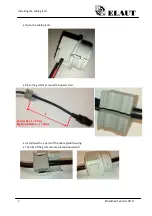
Страница 81: ...ent versie V0 0 Required material Power cord Cable gland 5 parts Mounting Plate Start position The cable gland and mounting plate are already assembled in the unit Mounting instructions Dismount the c...

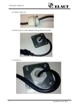
Страница 82: ...d 2 Document versie V0 0 Open the cable gland Place the grommet round the power cord Install now the 2 parts of the cable gland housing The ribs of the grommet are placed sidewards L Cosmic XL L 20 cm...

Страница 83: ...Installing the cable gland 3 Document versie V0 0 Install the rubber ring Slide the power cord with cable gland through the mounting plate Install the nut...

Страница 84: ...Installing the cable gland 4 Document versie V0 0 Connect the power cord to the power inlet END OF THE INSTRUCTIONS...

Страница 85: ...technical file Big One X treme 1 MANUAL 2 CABINETS 3 PRIMARY CIRCUITS 4 ELECTRONICS 5 FUNCTIONALITY 6 WIRING...

Страница 86: ...D BY A USER FOR A PARTICULAR PURPOSE THE REPRODUCTION DISTRIBUTION AND UTILISATION OF THIS DOCUMENT AS WELL AS THE COMMUNICATION OF ITS CONTENTS TO OTHERS WITHOUT EXPLICIT AUTHORIZATION IS PROHIBITED...

Страница 87: ...technical file Big One X treme 1 MANUAL 2 CABINETS 3 PRIMARY CIRCUITS 4 ELECTRONICS 5 FUNCTIONALITY 6 WIRING...

Страница 88: ...T 3 I 5 1 1 Mains power connection box 3 I 5 1 2 control cabinet 3 I 5 1 3 top lights supply 3 II FYSICAL PROPERTIES 4 II 1 STABILITYAND MECHANICALSAFETY 4 II 2 MOVING PARTS 4 II 3 ENCLOSURES 4 II 3 1...

Страница 89: ...panels with chipwood plate and glas panels inaccessably closed for non authorized personel The inside of the machine can be accessed by means of a key locked door Technical comparments are then acces...

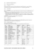
Страница 90: ...rical components refer to BO_xtreme_primary_schematic for details Following table contains components used in primary circuits Individual datasheet are found in addendum Id Article manufacturer Featur...

Страница 91: ...ith the test finger External enclosure parts withstand forces of 250 N applied by a testtool with a curved surface with radius of 30mm Enclosure parts protecting harardous areas withstand inpact of te...

Страница 92: ...wer The power supplies have current limiting features hiccup mode In case of total malfuction the mains fuse will limit current and power drawn from the mains power V ANNEXES V 1 ELECTRICAL RATING AND...

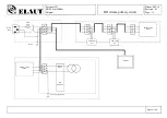
Страница 93: ...at 223 B9100 Sint Niklaas Belgium BO xtreme primary circuit Signed JDV chassis Main Fuse Mains Entry L E N Monitor SMPS 12VDC 200VA Power supply chassis L E N ITX SUPPLY Monitor L E N L E N L E N SMPS...

Страница 94: ...230 4 stromen 115 4 LEGENDE cont maximale continue stroom lag maximale stroom 1s na aanschakelen peek maximale stroom 10ms na aanschakelen peek2 peek na lange lijn of connectiepunt peek3 peek gedempt...

Страница 95: ...tyle 3266 Sleeving NOMEX MYLAR UL nr E93687 E34739 4 Insulation Supplier Polifibra GmbH Polyestertape class B 130 C Material manufacturer Ester Industries Ltd UL nr E121262 M UL94 HB according listing...

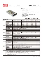
Страница 96: ...5 89 89 79 5 20A 115VAC 40A 230VAC 1mA 240VAC 105 135 rated output power 3 8 4 62V 4 5 5 6V 5 75 7V 9 4 10 9V 13 8 16 2V 2 88 3 5V Protection type Hiccup mode recovers automatically after fault condit...

Страница 97: ...ms 50ms 230VAC 3000ms 50ms 115VAC at full load 8ms at full load 230VAC 115VAC 88 264VAC 124 370VDC 47 63Hz PF 0 95 230VAC PF 0 98 115VAC at full load 89 5 89 5 89 90 90 89 20A 115VAC 40A 230VAC 2 5A 1...

Страница 98: ...tput with PFC Function HORIZONTAL Block Diagram PFC fosc 100KHz PWM fosc 100KHz PWM PFC CIRCUIT DETECTION O L P EMI FILTER RECTIFIERS POWER SWITCHING FILTER RECTIFIERS V V I P FG CONTROL O V P O T P I...

Страница 99: ...o s Model Encoding Description File Name LRS 150 SPEC 2016 05 11 Output voltage Series name LRS 150 12 easily meet the worldwide energy requirement LRS 150 has the complete protection functions and 5...

Страница 100: ...Compliance to EN61000 4 2 3 4 5 6 8 11 EN61000 6 2 EN50082 2 heavy industry level criteria A SAFETY EMC Note 7 EMC IMMUNITY EMC EMISSION OVER TEMPERATURE 87 5 88 5 89 90 12V 15V 24V 48V 12 5A 10A 6 5A...

Страница 101: ...32 170 200 220 240 260 264 90 100 80 70 60 50 40 170 264VAC 85 132VAC INPUT VOLTAGE VAC 60Hz LOAD 115VAC Input only 230VAC 30 0 25 20 10 30 40 20 40 50 80 60 100 60 50 70 HORIZONTAL 150W Single Output...

Страница 102: ...TPUT V FG AC L AC N 3 5 9 5 26 15 18 3 5 14 5 30 3 5 3 5 6 5 97 85 32 2 M 3 L 3 0 3 M3 L 5 4 5 152 5 1 2 3 4 5 6 7 8 LED SVR1 24 78 159 6 5 150 22 117 6 Installation Manual Please refer to http www me...

Страница 103: ...Mouser Electronics Authorized Distributor Click to View Pricing Inventory Delivery Lifecycle Information Mean Well LRS 150 48 LRS 150 24 LRS 150 36 LRS 150 15 LRS 150 12...

Страница 104: ...5V 2410 0231 1 4 kabel trafo config 230V 9015 0963 1 or 4 kabel trafo config 115V 9015 0964 1 5 zekering 5x20 1 60AT 2312 0016 1 or 5 zekering 5x20 3 15AT 2312 0035 1 7 kabel aarding 0 75 160mm 9015 0...

Страница 105: ...mentioned here may be the trademarks of their respective owners More info www lg com b2b youtube com c LGECommercialDisplay Apple App Store Google Play Store Download LG Commercial Display Mobile App...

Страница 106: ...nit mm Vesa 200 x 200 300 x 300 W x H x D weight With Stand 739 x 472 x 168 4 9kg 974 x 625 x 220 9 3kg 1 107 x 701 x 235 11 5kg 1 241 x 775 x 216 16 6kg W x H x D weight Packing 812 x 510 x 142 6 1kg...

Страница 107: ...missing txt datasheet missing Pagina 1...

Страница 108: ...5 N Y J X O A R N Y O Z 5 T T PUJS KPUN 8 2 7 D 2 3 Q 4 H 7 2 H 7 2 Y Y C Z H 7 2 8 H 5 2 U C Z U O _ 9 6 7 a O _ 9 a O _ 9 5 SVU SHTTHIPSP 9H PUN 3 B 3 5 8 8 0 H 8 R K C 2 H 5 6 2 D 1 5 V 8 R 1 H 5 6...

Страница 109: ...technical file Big One X treme 1 MANUAL 2 CABINETS 3 PRIMARY CIRCUITS 4 ELECTRONICS 5 FUNCTIONALITY 6 WIRING...

Страница 110: ...treme 9235 5015 button controls BO Grab motor 3500 9250 RGB ctrl SMPS 24V 150W 9092 0150 Big One supply 9239 0306 16 speaker dispenser head light 9040 7072 9040 7073 LED spotlight RGB ctrl RGB Ctrl 1...

Страница 111: ...urrent fuse connector label on LRS200 12 bottom amplifier 40 0 3 3 corners 5 46 00 1 00 50 6 4 2 corners 5 46 00 1 00 50 6 4 2 141 2 location type length pcs factor SMPS current fuse connector label o...

Страница 112: ...technical file Big One X treme 1 MANUAL 2 CABINETS 3 PRIMARY CIRCUITS 4 ELECTRONICS 5 FUNCTIONALITY 6 WIRING...

Страница 113: ...refer to machine manual...

Страница 114: ...technical file Big One X treme 1 MANUAL 2 CABINETS 3 PRIMARY CIRCUITS 4 ELECTRONICS 5 FUNCTIONALITY 6 WIRING...

Страница 115: ...320 9015 0969 9002 2331 9015 0939 Motor FWD BWD 3500 9130 9002 2332 9015 0939 Brake Motor Up Down Motor UP DOWN 9090 9005 3500 9240 3500 9130 3500 9470 Switch Hatch Switch Win Door Motor Hatch IR Dete...

Страница 116: ...WHITE N C 5 10 N C Lamp Lamp 9015 0940 2 1 FWD Black 2 SWD Green 4 3 U D Blue Claw En YELLOW 6 5 GND BLACK GTY out Yellow 8 7 N C SW2 Pink 10 9 SW4 Whi Gre SW6 Brown 1 12 11 N C N C 13 N C 15 14 Brown...

Страница 117: ...SW COM Orange SW4 Whi Gre 5 11 SW5 White SWD Green 2 6 SWD Grey FWD Black 1 5 FWD Brown Conn Mini fit 8p plug Claw Black 4 8 Claw Red U D Blue 3 7 U D White OUT Yellow 2 8 N C GND Black 1 7 V Red Conn...

Страница 118: ...V 4 White Det Out 3 IR Detector Switch Win Door Switch Hatch Motor Hatch 9015 0936 GND 30V Black 3 8 Mot Windoor Brown 1 SW Windoor Orange 4 9 SW Windoor Green 1 Conn Mini fit 10p rec 12V BROWN 2 7 SW...

Страница 119: ...Red R 4 5 G 3 Yellow V 6 Green 1 Blue B 2 Red R 4 5 G 3 Yellow V 6 Green 1 Blue B 2 Red R 4 5 G 3 Yellow V 6 Green 1 B 2 R 4 5 G 3 V 6 Domino 9002 2621 1 B 2 R 4 5 G 3 V 6 1 B 2 R 4 5 G 3 V 6 1 Blue B...

Страница 120: ...IR_NO Blue Lamp FIRE IR Grey 6 12 N C Lamp BWD SWL Purple 5 11 Lamp FWD SWR Brown Conn Mini fit 12p plug Yellow Black Purple Orange Pink Black Purple Orange 9015 0949 Grey Black Brown Orange Blue Bla...

Страница 121: ...5 G V R Yellow Red G Green B Blue 3 Yellow V 6 Green 1 Blue B 2 Red R 4 5 G 3 Yellow V 6 Green 5 2 Blue B Green G 4 1 Red R Yellow COM 6 3 Conn microfit 6p rec 5 2 Blue B Green G 4 1 Red R Yellow COM...

Страница 122: ...wn 12V 5 Yellow 2 Orange 3 Green GND 1 Conn JST xhp 5p plug Red 4 Brown 12V 5 Yellow 2 Orange 3 Green GND 1 4 Brown 12V 5 2 3 Green GND 1 Z From Gantry To Monitor P 3 3 2 Yellow 1 Black Yellow 4 Black...

Страница 123: ...technical file Big One X treme 1 MANUAL 2 CABINETS 3 PRIMARY CIRCUITS 4 ELECTRONICS 5 FUNCTIONALITY 6 WIRING ADDENDUM PARTS DATASHEETS...

Страница 124: ...0099 Print rgb led midden B UL94V 0 2 4831 0100 Print rgb led einde C UL94V 0 2 4831 0199 RGB Led board first A COMP UL94V 0 2 9015 1257 Kabel rgb connectie 1 2m 2 9015 1258 Kabel rgb connectie 3m 2 9...

Страница 125: ...coin wj ba 1 9015 1000 Kabel itx bill acceptor mars 1 COMPONENTS 1151 3500 Ntc 50r 2amp UL94V 0 1151 4100 Ntc 10r 3amp UL94V 0 1152 0135 Zekering ptc 1 35a st5 cURus TUV UL94V 0 1152 0400 Zekering pt...

Страница 126: ...CE UR CSA VDE 2450 0120 Teller 12v dc 6 digits NA 2510 0200 Draad 0 22 zwart UL AWM VW 1 2510 0201 Draad 0 22 bruin UL AWM VW 1 2510 0202 Draad 0 22 rood UL AWM VW 1 2510 0203 Draad 0 22 oranje UL AWM...

Страница 127: ...Refer to digital version for part datasheets...

Отзывы: