5
ECOWATER
S Y S T E M S
Unpacking & Installation
Bypass
Valve
Valve
Inlet
IN
OUT
FIG. 3A
Clip
Copper tube
O-ring
1. UNPACKING
EcoWater Systems conditioner/refiner models ,
, , , , ERM -
20CE+, and E are shipped from the
factory in one carton. The carton also includes a bag of small
parts needed to assemble and install the unit, plus this manu-
al.
Thoroughly check the EcoWater Systems conditioner/refiner
for possible shipping damage and parts loss. Also inspect and
note any damage to the shipping carton. Notify the transporta-
tion company if damage is present. EcoWater Systems is not
responsible for in-transit damages.
Remove and discard (RECYCLE) all packing materials. We
suggest you keep the small parts in the bag(s) until you are
ready to use them.
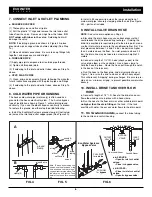
2. BRINE TANK (on two-tank models)
a.
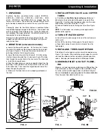
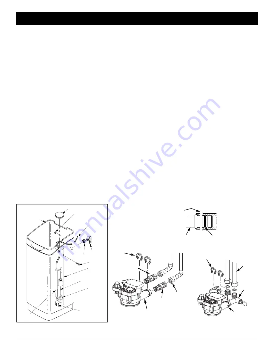
Locate the brinewell in position. On the brine tank, locate
the slots at the bottom of the brinewell, toward the tank wall,
as shown in Figure 2. Then use the screw and washer (in
parts bag) to fasten the brinewell in place.
b.
Lower the brine valve into the brinewell. Push the tubing
into the brinewell top slot (Fig. 2) and route it out of the brine
tank through the smaller hole in the rear wall of the brine tank.
c.
Install the brinewell cover.
d.
Take the rubber grommet and hose adaptor elbow from the
parts bag. Push grommet into the larger hole in the rear wall
of the brine tank. Then insert the larger diameter end of the
elbow through the grommet.
e.
Make sure the brine tank cover is properly positioned on
the tank
.
3. INSTALL BYPASS VALVE
and/or
COPPER
TUBES
a
. If installing an
EcoWater Systems Bypass Valve
, put
lubricated o-ring seals onto both bypass valve ports (See
Figure 3B). Carefully slide the bypass valve into the condi-
tioner/refiner valve and install the "C" clips.
b
. Connect flexible hoses to the bypass valve (See Figure
3B).
NOTE:
For lubrication, use silicone grease approved for
potable water supplies
.
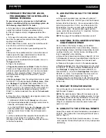
4. TURN OFF WATER SUPPLY
a
. Close the main water supply valve near the well pump or
water meter.
b
. Shut off the electric or fuel supply to the water heater.
c
. Open high and low faucets to drain all water from the
house pipes
.
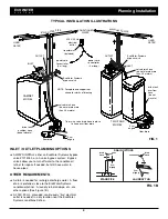
5. INSTALLING THREE-VALVE BYPASS
If installing a 3-valve bypass system, plumb as needed using
Figure 1 as a guide. When installing sweat copper, be sure to
use lead-free solder and flux, required by federal and state
codes. Use pipe joint compound on outside pipe threads
.
6. ASSEMBLE INLET & OUTLET PLUMB-
ING
Measure, cut, and loosely assemble pipe and fittings from the
main water pipe (or from the bypass valves installed in Step
5), to the inlet and outlet copper tubes, installed in Step 3b.
Be sure
hard water
supply pipe
goes to
the
valve inlet side
.
Trace the water flow direction to be sure.
FIG. 2
FIG. 3B
Valve
Inlet
1” NPT
Adapter
Clip
IN
OUT
FIG. 3
Use teflon tape,
pipe joint com-
pound or both
1” NPT
Sweat
Adapter
(2)
Clip
1” BSP
Flexible
Hose
screw
slots
brine valve
brinewell
brine tank
brine tubing
elbow
grommet
washer
brinewell cover
stand
tube
float stem


