20
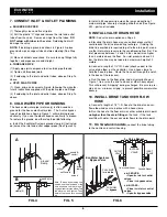
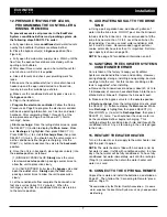
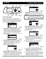
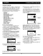
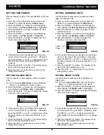
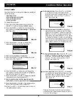
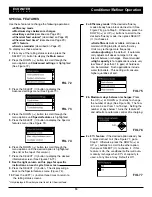
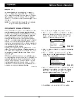
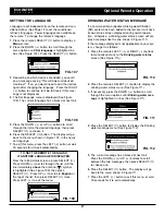
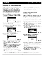
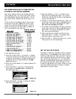
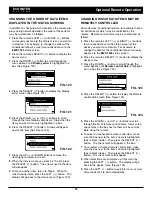
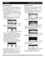
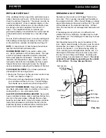
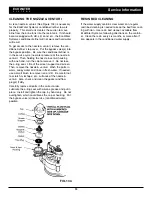
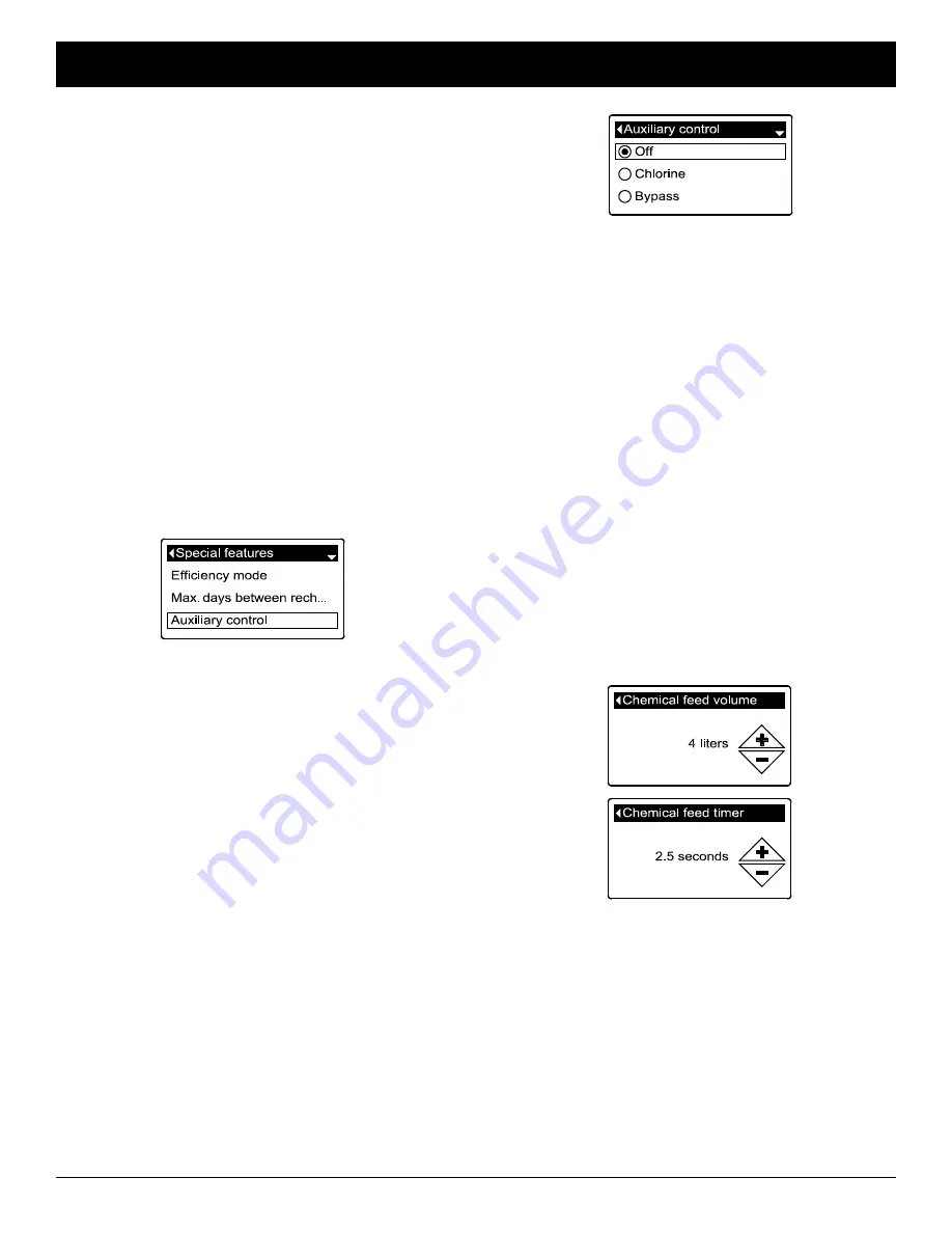
FIG. 80
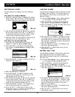
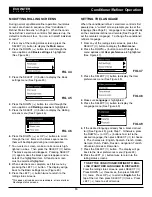
FIG. 81
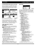
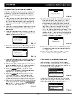
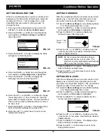
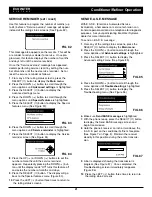
FIG. 78
AUXILIARY CONTROL
The electronic control has an auxiliary output which can
control external devices in a water treatment system.
The signal is 24V AC, current draw 800 mA maximum.
The Auxiliary Output terminals are located on the elec-
tronic control board (See Schematic on Page 39).
For more details on the use of auxiliary controlled
equipment in water treatment systems, consult the
EcoWater Systems “Problem Water Guide.”
To select an auxiliary control mode:
1
. From any of the rolling status screens, press the
SELECT (
¡
) button to display the
Main menu
.
2
. Press the DOWN (
6
) button to scroll through the
menu options until
Advanced settings
is highlighted.
3
. Press the SELECT (
¡
) button to display the
Advanced settings menu.
4
. Press the DOWN (
6
) button to scroll through the
menu options until
Special features
is highlighted.
5
. Press the SELECT (
¡
) button to display the Special
features menu (See Figure 78).
6
. Press the DOWN (
6
) button to scroll through the
menu options until
Auxiliary control
is highlighted.
7
. Press the SELECT (
¡
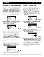
) button to display the Auxiliary
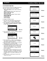
control menu (See Figure 79).
8
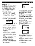
. If the desired option already has a black dot next to it
(See Figure 79), go to Step 9. Otherwise, press the
DOWN (
6
) or UP (
5
) buttons to scroll to the desired
option, then press SELECT (
¡
) to choose it.
=
Off
is the default.
=
Chlorine
can be used to drive a chlorine generator,
which produces chlorine, as brine water passes
through it, to sanitize the resin during recharges.
=
Bypass
turns 24V AC on during the entire regener-
ation cycle (when the conditioner/refiner’s valve is
in bypass and hard water is being supplied to the
house).
=
Chemical feed
can be used to run a chemical feed
pump. If chosen, the chemical feed volume and
timer must be set, as detailed at right)
=
Water use
turns 24V AC on when the conditioner/
refiner’s turbine indicates water flow. Could drive
an air pump for iron or sulfur oxidation.
9
. Press the SELECT (
¡
) button. The display will go
back to the Special features menu (Figure 78).
10
. Press the LEFT (
3
) button three times to return to
the rolling status screens.
FIG. 79
CHEMICAL FEED
If the auxiliary control mode has been set to
Chemical
feed
, as described in the previous section, two addition-
al lines (
Chemical feed volume
and
Chemical feed
timer
) will appear on the Special features menu.
To set these values:
1
. From any of the rolling status screens, press the
SELECT (
¡
) button to display the
Main menu
.
2
. Press the DOWN (
6
) button to scroll through the
menu options until
Advanced settings
is highlighted.
3
. Press the SELECT (
¡
) button to display the
Advanced settings menu.
4
. Press the DOWN (
6
) button to scroll through the
menu options until
Special features
is highlighted.
5
. Press the SELECT (
¡
) button to display the Special
features menu (See Figure 78).
6
. Press the DOWN (
6
) button to scroll through the
menu options until
Chemical feed volume
or
Chemical feed timer
is highlighted.
7
. Press the SELECT (
¡
) button to display the
Chemical feed volume or Chemical feed timer menu
(See Figures 80 & 81).
8
. Press the UP (
5
) or DOWN (
6
) buttons to change
the value. Hold the button down to rapidly advance.
=
Chemical feed volume
is the amount of water
which will pass through the conditioner/refiner
between each activation of the chemical feed
equipment.
=
Chemical feed timer
is how long the output to the
chemical feed equipment is energized each time it
is activated.
9
. Press the SELECT (
¡
) button. The display will go
back to the Special features menu (Figure 78).
10
. Press the LEFT (
3
) button three times to return to
the rolling status screens.
ECOWATER
S Y S T E M S
Conditioner/Refiner Operation

