6
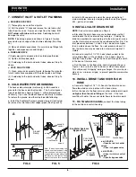
7. CONNECT INLET & OUTLET PLUMBING
a. SOLDERED COPPER
(1) Thoroughly clean and flux all joints.
(2) Pull the plastic “C'' clips and remove the inlet and outlet
tubes from the valve. Remove o-rings from the tubes.
DO
NOT solder with tubes in the valve.
Soldering heat will
damage the valve.
NOTE:
If installing a ground as shown in Figure 4A, place
ground clamps on copper tubes before soldering (See Step
7a).
(3) Make all solder connections. Be sure to keep fittings fully
together, and pipes square and straight.
b. THREADED PIPE
(1) Apply pipe joint compound to all outside pipe threads.
(2) Tighten all threaded joints.
(3) If soldering to the inlet and outlet tubes, observe Step 7a
above.
c. CPVC PLASTIC PIPE
(1) Clean, prime and cement all joints, following the manufac-
turer's instructions supplied with the plastic pipe and fittings.
(2) If soldering to the inlet and outlet tubes, observe Step 7a
above.
8. COLD WATER PIPE GROUNDING
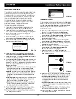
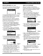
The house cold water pipe (metal only) is often used as a
ground for the house electrical system. The 3-valve bypass
type of installation, shown in Figure 1, will maintain ground
continuity. If you use the plastic bypass, continuity is broken.
To restore the ground, do either step
8a
or
8b
following.
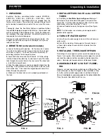
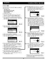
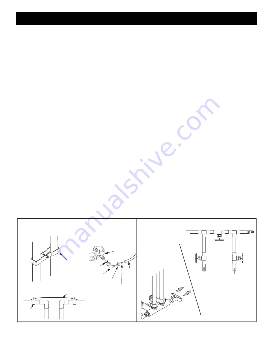
a
. Install the EcoWater Systems ground clamp kit (not includ-
ed) across the inlet and outlet copper pipes (See Figure 4A).
b
. Install a #4 copper wire across the removed section of
main water pipe, securely clamping at both ends (See Figure
4B) – parts not included.
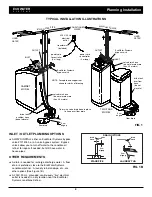
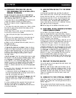
9. INSTALL VALVE DRAIN HOSE
NOTE:
See valve drain options on Page 4.
a
. Elevating the drain hose may cause back pressure that
could reduce the brine draw during recharge. If raising the
drain line overhead is required to get to the drain point, meas-
ure the inlet water pressure to the conditioner/refiner first. For
inlet pressures between 1.4 and 3.4 bar, do not raise higher
than 2 meters above the floor. For inlet pressure above 3.4
bar, the drain line may be raised to a maximum height of 3
meters.
b
. Connect a length of 1/2" I.D. hose (check codes) to the
valve drain elbow, on the controller. Use a hose clamp to
hold the hose in place. Route the hose out through the notch
in the back of the top cover.
c
. Run the hose to the floor drain, and as typically shown in
Figure 1, tie or wire the end to a brick or other heavy object.
This will prevent “whipping” during recharges. Be sure to pro-
vide a 4 cm minimum air gap, to prevent possible sewer water
backup.
10. INSTALL BRINE TANK OVERFLOW
HOSE
a
. Connect a length of 1/2" I. D. hose to the brine tank over-
flow elbow and secure in place with a hose clamp.
b
. Run the hose to the floor drain, or other suitable drain point
no higher than the drain fitting
on the tank. If the tank
overfills with water, the excess water flows to the drain point.
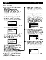
11. On Two-tank models,
connect the brine tubing
to the nozzle and venturi housing.
FIG. 4
FIG. 5
FIG. 6
ECOWATER
S Y S T E M S
Installation
ground wire
clamp (2)
nozzle &
venturi
o--ring
elbow
Note: To ease brine tubing con-
nection, use the elbow and o--ring
seal as shown. Lubricate the o--
ring and insert into the elbow. Turn
the elbow on and tighten. Then,
back--off up to one turn, as need-
ed.
B
A
3 -- Valve Bypass
OUTLET
VALVE
INLET
VALVE
BYPASS
VALVE
to conditioner
from conditioner
EcoWater Systems
Bypass Valve
D
for
SERVICE:
-- Open
the
inlet
and
outlet
valves.
-- Close
the
bypass valve.
D
for
BYPASS:
-- Close
the
inlet
and
outlet
valves.
-- Open
the
bypass valve.
PUSH
IN
for
bypass
PULL
OUT
for
service
nut--ferrule
screen
ground
clamp
brine
tubing


