3 Installation
3.6 Electrical Installation
82
DC1-S…20…, DC1-S…OE1 Variable Frequency Drives
05/21 MN040058EN
www.eaton.com
3.6.2.6 Control signal terminals IP66
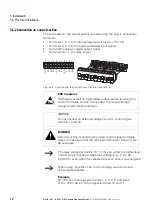
In the case of DC1-S… variable frequency drives with an IP66 degree of
protection, the plug-in control signal terminals are located under the terminal
cover. In version DC1-…A6SN, the local controls will already be connected.
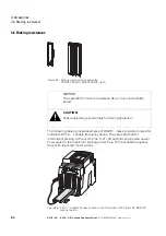
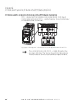
Figure 55: DC1-…A6S… (connection wired at the factory)
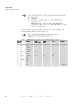
When supplied, the control signal terminals will be connected as follows:
Table 14: Configuration of the control signal terminals
When the device is set to its default settings, the setpoint value for operation
can be set using the potentiometer. The REV – 0 – FWD selector switch can
be used to start the single-phase AC motor.
Pin
Colour
Function
1
RD (red)
+24 V to FWD/REV selector switch
2
BU (blue)
From selector switch = FWD (Start)
3
YE (yellow)
From selector switch = REV (works as quick stop
in this case)
5
GN (green)
+10 V to potentiometer
6
WH (white)
From potentiometer = REF
7
BK (black)
0 V to potentiometer
REV
FWD
0
ON
OFF
PWR
1 2 3 4 5 6 7 8 9 10 11
U
V
W
L1/N L2/N
L3
⏚
⏚
1 2 3 4 5 6 7 8 9 10 11
1 2 3 4 5 6 7 8 9 10 11
+24 V
DI1
AI1
0 V
DI2
DI3
AO1
0 V
K13
K14
+10 V
BK
WH
GN
YE
BU
RD
Содержание PowerXL
Страница 4: ......
Страница 124: ...5 Operation 5 7 Handling the keypad 120 DC1 S 20 DC1 S OE1 Variable Frequency Drives 05 21 MN040058EN www eaton com...
Страница 160: ...6 Parameter structure 6 7 Fault messages 156 DC1 S 20 DC1 S OE1 Variable Frequency Drives 05 21 MN040058EN www eaton com...
Страница 170: ...7 Technical Data 7 3 Dimensions 166 DC1 S 20 DC1 S OE1 Variable Frequency Drives 05 21 MN040058EN www eaton com...

