3 Installation
3.6 Electrical Installation
DC1-S…20…, DC1-S…OE1 Variable Frequency Drives
05/21 MN040058EN
www.eaton.com
71
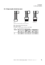
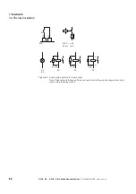
The following figure shows the layout for a three-core, screened motor cable
(recommended configuration).
Figure 43: Example: screened motor cable
a
Cu shield braid
b
PVC outer casing
c
Flexible wire (copper strands)
d
PVC core insulation, 1 x green-yellow and 2 x black (or 1 x black + 1 x blue)
e
Textile and PVC fillers
If additional subassemblies (such as contactors, overload relays, or terminals)
are found in a motor feeder, the motor cable’s screening can be interrupted
close to these assemblies and terminated to the metal mounting plate (PES)
in such a way that electrical contact is established across a large surface
area. Exposed, i.e., unscreened connecting cables should not be longer than
approx 300 mm (max. 500 mm).
→
In the case of units with a frame size of FS1 and FS2 the
screened motor cable can also be connected using an EMC
cable bracket (DX-EMC-MNT…M)
②
①
⑤
③
④
Содержание PowerXL
Страница 4: ......
Страница 124: ...5 Operation 5 7 Handling the keypad 120 DC1 S 20 DC1 S OE1 Variable Frequency Drives 05 21 MN040058EN www eaton com...
Страница 160: ...6 Parameter structure 6 7 Fault messages 156 DC1 S 20 DC1 S OE1 Variable Frequency Drives 05 21 MN040058EN www eaton com...
Страница 170: ...7 Technical Data 7 3 Dimensions 166 DC1 S 20 DC1 S OE1 Variable Frequency Drives 05 21 MN040058EN www eaton com...


