IM05805016K
For more information visit:
www.chfire.com
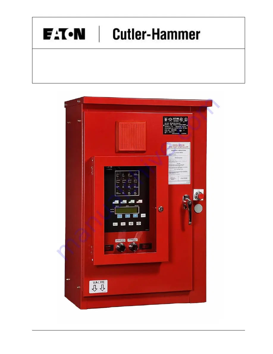
Diesel Engine Fire Pump Controllers
Instructions
Страница 1: ...IM05805016K For more information visit www chfire com Diesel Engine Fire Pump Controllers Instructions...
Страница 2: ......
Страница 3: ...TIMER 4 6 PROGRAMMING OF THE MAIN CONTROLLER 4 6 1 TO PROGRAM THE CONTROLLER 4 6 2 PROGRAM DESCRIPTIONS 4 6 2 1 Change Date 5 6 2 2 Change Time 5 6 2 3 Weekly Timer 5 6 2 4 Run Period Timer 5 6 2 5 L...
Страница 4: ...FIELD FAILURE ALARM SIMULATION 13 13 1 CHARGER FAILURE 13 13 2 BATTERY FAILURE 13 13 3 LOW OIL PRESSURE 13 13 4 HIGH ENGINE TEMPERATURE 13 13 5 ENGINE FAIL TO START 13 13 6 ENGINE OVERSPEED 13 13 7 OT...
Страница 5: ...ine battery voltage and system pressure Inspect all electrical connections components and wiring for any visible damage and correct as necessary Ensure that all electrical connections are tightened be...
Страница 6: ...reading of each battery as well as the system pressure in PSI The LCD display is also used while programming the diesel controller 4 2 Annunciators The alarm and status indicators are located in the t...
Страница 7: ...ll further cranking 5 4 Stop Modes The Stop Mode is programmable for either Manual Stop or Auto Stop see Figure 2 Note that the engine can be stopped at any time by placing the controller in the OFF p...
Страница 8: ...a few seconds delay will prevent the lead pump controller from responding to momentary hydraulic transient pressure loss which would otherwise start the fire pump unnecessarily The SST can be program...
Страница 9: ...grammed determines at what pressure the controller will initiate a start command to the engine The pressure range is 1 500 PSI Factory default 1 PSI 6 2 8 Pressure Stop Point The value programmed dete...
Страница 10: ...programming menu If selected as YES after exiting the program mode and pressing the Time Print button for 3 seconds the programmed parameters and selected controller readings will be printed This is...
Страница 11: ...rger is fully electronic and will protect itself by shutting down during a continued short circuit The maximum current draw that the chargers will draw when operating at 100 charging rate is 12 Volt S...
Страница 12: ...t on the load side of the charger In addition the charger will not operate if a battery is connected incorrectly or if the wrong voltage of battery is connected AC Input Fuse Protection The AC Supply...
Страница 13: ...ly after applying power to the charger with DIP Switch 8 in the ON position and a battery connected When the charger is in the forced charge mode it will attempt to recover a battery by delivering 10...
Страница 14: ...ll sound if system overpressure is present 11 Electronic Starting Engines ECM The FD100 diesel engine fire pump controllers are compatible with NFPA20 Section 12 4 1 3 for engines with ECM Electronic...
Страница 15: ...ection 14 of manual Depress the AUTO button LED on AUTO button will light and Annunciator Switch in Auto will illuminate Ensure that water pressure is available and the LCD display on the Display Pane...
Страница 16: ...d will energize and reduce pressure Controller will start engine automatically Engine Run annunciator illuminates Press OFF button Engine will stop NOTE Engine will stop if Low Oil Pressure High Water...
Страница 17: ...rm will also indicate if terminal 4 is wired from the engine to the panel and the engine is not physically running 13 5 Engine Fail to Start ALL ENGINES EXCEPT CATERPILLAR 1 Disconnect field wires 9 1...
Страница 18: ...el It is recommended that square and clean cut edge is used for entry of paper into the printer mechanism scissor cut preferred To load paper turn on the power Now feed the cut edge of the paper into...
Страница 19: ...PRINTER UNTIL ALL MESSAGES ARE PRINTED OTHERWISE INFORMATION WILL BE LOST 14 5 Print Status When programmed as YES the printer will print the STATUS of the controller upon exiting the program mode and...
Страница 20: ...stores See list below depicting the office supply stores and their respective catalog number for the paper NON TAPED ENDED ROLLS WILSONS LAB CR722 TAPED ENDED ROLLS STAPLES 14485 GRAND TOY 7767000 OFF...
Страница 21: ...AKE INSTRUCTION FROM LCD DISPLAY HOLD BUTTON FOR AT LEAST 3 SEC THEN PRINTERWILL PRINT ANY AVAILABLE INFORMATION 4 FOR DETAIL AND SET UP REFERTO OPERATING MANUAL 5 TO MANUALLY STARTTHE DIESEL DEPRESST...
Страница 22: ...REASE COUNT UNLESS OTHERWISE SHOWN DECREASE COUNT UNLESS OTHERWISE SHOWN INCREASE COUNT LANG ENGLISH YEAR 98 HOUR 15 DAY MON RPT MINUTES 30 PRES TRANS YES START 100 PSI STOP 110 PSI INPUT OUTPUT INPUT...
Страница 23: ...t Current 11 A 11 A Battery Voltage 8 0V 18 0V 18 0 V 31 4 V Ambient Temperature 60 C 60 C Table 2 Threshold 12V Battery 24V Battery Bulk Overcharge Float Bulk Overcharge Float Min Max Min Max Min Max...
Страница 24: ...Controller Panel Pressing RESET On Controller Panel Pump Room PRT Eliminate Problem and Press RESET MM DD YR HH MM SS Fuel Spill mode High Engine Temperature 5 Placing Controller in the OFF Mode Plac...
Страница 25: ...rint MM DD YR HH MM SS Fuel Solenoid Open mode Low Pressure This message is printed when the controller is called upon to start the diesel engine as a result of low system pressure MM DD YR HH MM SS L...
Страница 26: ...CB1 CRANK 2 CB2 Dimensions Standard Enclosure Type NEMA 2 12 NOTES 1 All enclosures finished in FirePump red 2 Cable entrance bottom only 3 Standard enclosure type NEMA 2 12 4 Enclosure made from 14...
Страница 27: ...NECTION DIAGRAM IS SUITABLE FOR THE FOLLOWING DIESEL ENGINES CLARKE DETROIT DIESEL ALLISON MODELS DDFP O3DT DDFP L3DT DDFP T3DT JDFP O6WA JDFP O6WR DDFP T6FA DDFP O6FA DDFP O6FH DDFP L8FA DDFP O8FA DD...
Страница 28: ...D IS ISOLATED FROM CABINET GROUND 4 REFER TO CONTROLLER NAMEPLATE FOR PROPER POWER SUPPLY REQUIREMENTS THIS DIESEL CONTROLLER DRAWS 15AMPS MAX 5 FOR CATERPILLER ENGINES ONLY 6 AFTER 1987 MOST ENGINE D...
Страница 29: ...the bottom right side ONLY Compare rating nameplates on controller and engine All Electrical Connections are tight All Wiring to and from Controller is Correct Field Connections Remote Starters Fuel L...
Страница 30: ...t value is 10 PSI Set Sequential Start Timer If required Set Stop Mode to either Manual or Automatic Enable Disable AC Failure Start Set Print Routine to Automatic This will be set back to manual when...
Страница 31: ...Place the controller in the AUTO mode by depressing the AUTO button At the programmed date and time the drain valve solenoid will open and the pressure will drop The engine will run for a minimum of...
Страница 32: ...Failure and Charger 2 Failure should illuminate after 3 minutes Reconnect AC power Press the OFF button to reset the alarms Fail to Start Place the controller in the AUTO mode by depressing the AUTO...
Страница 33: ...Stop Point Low Pressure Alarm Pressure Deviation Sequential Start Timer If required Enable Disable Manual Stop as per requirements Enable Disable AC Failure Start If Required Print Routine When finish...
Страница 34: ...Hammer 2256 29th Street NE 10 Calgary Alberta T1Y 7G4 Canada Tel 403 717 2000 Fax 403 717 0567 www chfire com 2007 Eaton Corporation All Rights Reserved Printed in Canada Publication No IM05805016K O...