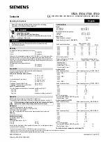
manualshive.com logo in svg
background image


PUB 50411


D64RP18 SERIES B1 DIGITAL GROUND FAULT RELAY 


Revision 2 

May, 2005 

Page 3 


1. 

GENERAL DESCRIPTION


The 

D64RP18

 is a microprocessor based ground fault relay for use on solidly grounded or resistance 

grounded systems. This innovative digital electronic relay measures ground fault current using a built-in 1.1” 

zero sequence current transformer (CT). 


The 

D64RP18

 reacts to alternating current only and will reject direct current signals. It will maintain accuracy 

over a frequency range of 45 to 450Hz, making it suitable for variable frequency drive applications. 


660 Volts is the maximum system operating voltage for the D64RP18 when passing the system power 

conductors through the built-in CT. However, by using any Eaton’s Cutler-Hammer C311CT zero sequence 

current transformers with 500:1 ratio, connecting the secondary to terminals T1 and T2 of the relay, and 

passing the system insulated power conductors through the window of this CT, the D64RP18 can be applied 

on any system voltage.  


The ground fault current trip level is set on a front accessible binary DIPswitch array. Trip currents from 30 

milliamps - 6 Amps can be selected in 8 discrete steps. These same trip settings are available when using any 

C311CT 500:1 ratio external CT. The trip level can be set just above the charging current

1

. Any deterioration in 

the circuit will trip the relay. This also permits scheduled field testing of the relay (by lowering the trip level).  


1

 The capacitance-to-ground charging current on a system will vary depending on: the overall length of 

the cables; the types of loads; the quality of insulation on the phase conductors; the surrounding 

equipment grounding, cable trays, junction boxes, etc.; and, the type of transformer. 


A "Rule-of-Thumb" for systems 600 Volts and lower: The charging current is 0.5 Amps per 1000 kVA 

of transformer capacity. 


The response time on ground fault trip is set on a single front accessible DIPswitch. The two settings are 

instantaneous (20 ms) or 500 ms.  


The output relay has Form “Z” (4 terminal) N.O. and N.C. contacts which may be used to operate the upstream 

protective device and to indicate a failure of the system. The relay will operate in one of two modes: Non-

failsafe; or Pulsed Output Auto Reset. The mode is established by the type of pushbutton (or jumper) 

connected to terminals R1 and R2: N.O. = Non-failsafe; N.C. (or jumper) = Pulsed Output Auto Reset. 


By double clicking the remote RESET button connected to terminals R1 and R2, a functional test of the 

D64RP18 is invoked. A single press of a N.O. contact remote RESET button resets the relay after a trip. (It is 

not necessary to press a N.C. contact remote RESET to invoke Auto Reset). The green LED indicates two 

functions: When slow flashing it denotes control power is applied to terminals N- and L+; when fast blinking it 

denotes the relay has sensed a ground fault current higher than the trip level for a period longer than the trip 

time and that the output contacts have operated.    


A 10 point Pull-apart terminal block simplifies connection of field wiring. 


The D64RP18 operates on any control voltage from 24 to 240 Volts ac or dc. 


2. 

OPERATION


2.1 

GLOSSARY OF TERMS


Manual Reset:


A N.O. contact remote RESET pushbutton connected to terminals R1 and R2 of the D64RP18 

must be pressed once to reset the output relay after a trip, providing the ground fault has been 

cleared or the measured values are within the preset limits.  

Содержание Cutler-Hammer D64RP18

Страница 1: ...eration Eaton Electrical 3228 South Service Road 4201 North 27th Street Burlington Ontario Milwaukee WI L7R 3Y8 53216 TEST RESET PUSHBUTTON N L POWER SUPPLY N O CONTROL CIRCUIT N C CONTROL CIRCUIT EXT...

Страница 2: ...TE 7 2 5 INDICATION 7 2 6 RESET 7 2 7 GROUND FAULT TEST 7 3 INSTALLATION INSTRUCTIONS 7 3 1 MOUNTING 8 3 2 BUILT IN CURRENT TRANSFORMER 8 3 3 EXTERNAL CURRENT TRANSFORMER 8 3 4 CONNECTIONS 8 3 4 1 CON...

Страница 3: ...n on the phase conductors the surrounding equipment grounding cable trays junction boxes etc and the type of transformer A Rule of Thumb for systems 600 Volts and lower The charging current is 0 5 Amp...

Страница 4: ...s restored the relay will trip and the green LED will resume fast blink after 500 milliseconds regardless of the time delay set on the Trip Delay DIPswitch and the above cycle will be repeated If the...

Страница 5: ...s 100 Amps continuous Any Eaton s Cutler Hammer C311CT with 500 1 ratio may be used when the above requirements dictate the use of an external CT The ground fault trip current setting range of 30 mA 6...

Страница 6: ...rrent exceeds the TRIP LEVEL setting the output relay changes state after the pre selected TRIP DELAY time 2 2 2 GROUND FAULT TRIP DELAY TIME DIPSWITCH 4 The ground fault TRIP DELAY time can be set at...

Страница 7: ...the unit After the trip if the external button is N O the trip mode is Non Failsafe the output relay will remain tripped and the green LED will fast blink until the button is pressed Manual Reset Afte...

Страница 8: ...maximum continuous primary phase current is to be 100 Amps 3 3 EXTERNAL CURRENT TRANSFORMER Refer to the Glossary of Terms to determine if an external Current Transformer is required for the applicat...

Страница 9: ...rrent transformer and a typical connection of an ac motor starter coil 1M A remote Reset button with N O contacts is connected to terminals R1 and R2 providing Non Failsafe operating mode Comparing th...

Страница 10: ...80 to 110 of rated voltage 24 240 V dc Under voltage tolerance no impaired operation withstands loss of supply up to 100 ms Power Up Time 500 milliseconds Maximum System Voltage Frequency 660 Volts a...

Страница 11: ...ms 19 35 ms 500 ms 546 579 ms 523 542 ms 512 529 ms 506 523 ms Ground Fault Trip Current Level 30 mA 6 0 Amps in 8 settings 30mA 120mA 210mA 300mA 600mA 2 4Amps 4 2Amps and 6 0Amps Setting within the...

Страница 12: ...ty EN 61000 4 4 Electromagnetic compatibility EMC for industrial process measurement and control equipment Part 4 4 Electrical fast transient burst immunity EN 61000 4 5 Electromagnetic compatibility...

Страница 13: ...R1 R2 PULSED AUTO RESET Closed Contacts on Terminals R1 R2 13 14 11 12 13 14 11 12 1 CONTROL POWER OFF 2 CONTROL POWER ON 3 CONTROL POWER ON FAULT CURRENT ABOVE TRIP SETTING TRIP TIME 4 CONTROL POWER...

Страница 14: ...CORE BALANCE 1M O L GROUNDED SYSTEMS 1 Phase 2 wire 1 Phase 3 wire 3 Phase 3 wire 3 Phase 4 wire POWER SOURCE CURRENT CARRYING NEUTRAL WHEN USED R 1M 1M START STOP O L TRIP RESET DOUBLE CLICK FOR TEST...

Страница 15: ...AND PULSED TRIP AUTO RESET GROUNDED SYSTEMS 1 Phase 2 wire 1 Phase 3 wire 3 Phase 3 wire 3 Phase 4 wire POWER SOURCE CURRENT CARRYING NEUTRAL WHEN USED ST DOUBLE CLICK FOR TEST T PULSED TRIP AUTO RESE...

Страница 16: ...IEW OPEN WEIGHT 0 88 LBS 40KG PACKAGED WEIGHT 1 08 LBS 49 KG DIMENSIONS ARE IN INCHES MM IN BRACKETS FIGURE 3 DIMENSIONS AND WEIGHTS D64RP18 REAR PANEL MOUNTING DIN RAIL OR 2 SCREW 3 58 91 1 38 35 2 7...

Страница 17: ...IND LED should fast blink This procedure tests the functionality of the unit RESETTING THE D64RP18 AFTER GROUND FAULT TRIP TEST If the remote button is a N O device the D64RP18 is in the non failsafe...

Отзывы: