manualshive.com logo in svg
background image


PUB 50411


D64RP18 SERIES B1 DIGITAL GROUND FAULT RELAY 


Revision 2 

May, 2005 

Page 11 


A simulated current equal to 120% of the trip current set on the Trip Level DIPswitches 

replaces the measured current. This tests all internal electronics and secondary winding of the 

built-in current transformer. No external power supply or additional wiring is required. 


Remote Test ........................................................ Double click button connected to terminals R1 and R2 


Remote Reset (Non-Failsafe mode only) ..............N.O. Reset button connected to terminals R1 and R2 


Reset mode ...............................................................................................  Manual or Pulsed Auto Reset 


Ground Fault Circuit: 


Ground Fault Trip Time Delay......................................................................... 20 or 500 milliseconds 


Setting ............................................................................................ DIPswitch 4 on front of relay 


Accuracy: 


Has a current dependent behavior: 


If set for 

Delay when current exceeds trip current setting by a factor of 


1.2 


20 ms 

59-91 ms 

36-54 ms 

25-41 ms 

19-35 ms 


500 ms 

546-579 ms 

523-542 ms 

512-529 ms 

506-523 ms 


Ground Fault Trip Current Level 

30 mA – 6.0 Amps in 8 settings: 30mA, 120mA, 210mA, 

300mA, 600mA, 2.4Amps, 4.2Amps, and 6.0Amps 


Setting within the Range.................................................DIPswitches 1, 2, & 3, on front of relay 


Accuracy ...............................................................................................+0%, -15% of trip setting 


Note:  The accuracy of the trip point refers to the value of the real world current 

(assuming a purely sinusoidal wave shape) that just causes a trip, with 

respect to the specified value in the table. 


Frequency Response Range ............................................................................................45 - 450 Hz 


Thermal Characteristics: 


Short Time Withstand: 


1000A..................................................................................................................... 1 second 


2000A.................................................................................................................. 0.1 second 


Environment: 


Operating Temperature........................................................................................-35

°

C to +60

°


Storage ................................................................................................................-40

°

C to +80

°


Humidity .................................................................................................85% (No Condensation) 


Shock resistance ..................................................................................................... 10G (no malfunction) 


Vibration resistance....................................10G, 10-55 Hz at 1.5 mm double amplitude (no malfunction) 


Ingress protection ...............................................................................................................................IP20 


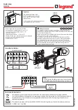
Dimensions (refer to Figure 3): 


Height.....................................................................................................................2.76" (70 mm) 


Width......................................................................................................................1.77" (45 mm) 


Depth (not including terminal blocks).....................................................................3.58" (91 mm) 


Depth (including terminal blocks)..................................................................... 4.43” (112.5 mm) 


Mounting (refer to Figure 3): 


DIN rail .............................................................................................................................. 35 mm 

Содержание Cutler-Hammer D64RP18

Страница 1: ...eration Eaton Electrical 3228 South Service Road 4201 North 27th Street Burlington Ontario Milwaukee WI L7R 3Y8 53216 TEST RESET PUSHBUTTON N L POWER SUPPLY N O CONTROL CIRCUIT N C CONTROL CIRCUIT EXT...

Страница 2: ...TE 7 2 5 INDICATION 7 2 6 RESET 7 2 7 GROUND FAULT TEST 7 3 INSTALLATION INSTRUCTIONS 7 3 1 MOUNTING 8 3 2 BUILT IN CURRENT TRANSFORMER 8 3 3 EXTERNAL CURRENT TRANSFORMER 8 3 4 CONNECTIONS 8 3 4 1 CON...

Страница 3: ...n on the phase conductors the surrounding equipment grounding cable trays junction boxes etc and the type of transformer A Rule of Thumb for systems 600 Volts and lower The charging current is 0 5 Amp...

Страница 4: ...s restored the relay will trip and the green LED will resume fast blink after 500 milliseconds regardless of the time delay set on the Trip Delay DIPswitch and the above cycle will be repeated If the...

Страница 5: ...s 100 Amps continuous Any Eaton s Cutler Hammer C311CT with 500 1 ratio may be used when the above requirements dictate the use of an external CT The ground fault trip current setting range of 30 mA 6...

Страница 6: ...rrent exceeds the TRIP LEVEL setting the output relay changes state after the pre selected TRIP DELAY time 2 2 2 GROUND FAULT TRIP DELAY TIME DIPSWITCH 4 The ground fault TRIP DELAY time can be set at...

Страница 7: ...the unit After the trip if the external button is N O the trip mode is Non Failsafe the output relay will remain tripped and the green LED will fast blink until the button is pressed Manual Reset Afte...

Страница 8: ...maximum continuous primary phase current is to be 100 Amps 3 3 EXTERNAL CURRENT TRANSFORMER Refer to the Glossary of Terms to determine if an external Current Transformer is required for the applicat...

Страница 9: ...rrent transformer and a typical connection of an ac motor starter coil 1M A remote Reset button with N O contacts is connected to terminals R1 and R2 providing Non Failsafe operating mode Comparing th...

Страница 10: ...80 to 110 of rated voltage 24 240 V dc Under voltage tolerance no impaired operation withstands loss of supply up to 100 ms Power Up Time 500 milliseconds Maximum System Voltage Frequency 660 Volts a...

Страница 11: ...ms 19 35 ms 500 ms 546 579 ms 523 542 ms 512 529 ms 506 523 ms Ground Fault Trip Current Level 30 mA 6 0 Amps in 8 settings 30mA 120mA 210mA 300mA 600mA 2 4Amps 4 2Amps and 6 0Amps Setting within the...

Страница 12: ...ty EN 61000 4 4 Electromagnetic compatibility EMC for industrial process measurement and control equipment Part 4 4 Electrical fast transient burst immunity EN 61000 4 5 Electromagnetic compatibility...

Страница 13: ...R1 R2 PULSED AUTO RESET Closed Contacts on Terminals R1 R2 13 14 11 12 13 14 11 12 1 CONTROL POWER OFF 2 CONTROL POWER ON 3 CONTROL POWER ON FAULT CURRENT ABOVE TRIP SETTING TRIP TIME 4 CONTROL POWER...

Страница 14: ...CORE BALANCE 1M O L GROUNDED SYSTEMS 1 Phase 2 wire 1 Phase 3 wire 3 Phase 3 wire 3 Phase 4 wire POWER SOURCE CURRENT CARRYING NEUTRAL WHEN USED R 1M 1M START STOP O L TRIP RESET DOUBLE CLICK FOR TEST...

Страница 15: ...AND PULSED TRIP AUTO RESET GROUNDED SYSTEMS 1 Phase 2 wire 1 Phase 3 wire 3 Phase 3 wire 3 Phase 4 wire POWER SOURCE CURRENT CARRYING NEUTRAL WHEN USED ST DOUBLE CLICK FOR TEST T PULSED TRIP AUTO RESE...

Страница 16: ...IEW OPEN WEIGHT 0 88 LBS 40KG PACKAGED WEIGHT 1 08 LBS 49 KG DIMENSIONS ARE IN INCHES MM IN BRACKETS FIGURE 3 DIMENSIONS AND WEIGHTS D64RP18 REAR PANEL MOUNTING DIN RAIL OR 2 SCREW 3 58 91 1 38 35 2 7...

Страница 17: ...IND LED should fast blink This procedure tests the functionality of the unit RESETTING THE D64RP18 AFTER GROUND FAULT TRIP TEST If the remote button is a N O device the D64RP18 is in the non failsafe...

Отзывы: