


8
Instruction Booklet
IB48050
Effective September 2012
Instructions for installation,
operation, and maintenance of the
AMPGARD 15 kV, 300A vacuum starter
eaton Corporation
www.eaton.com
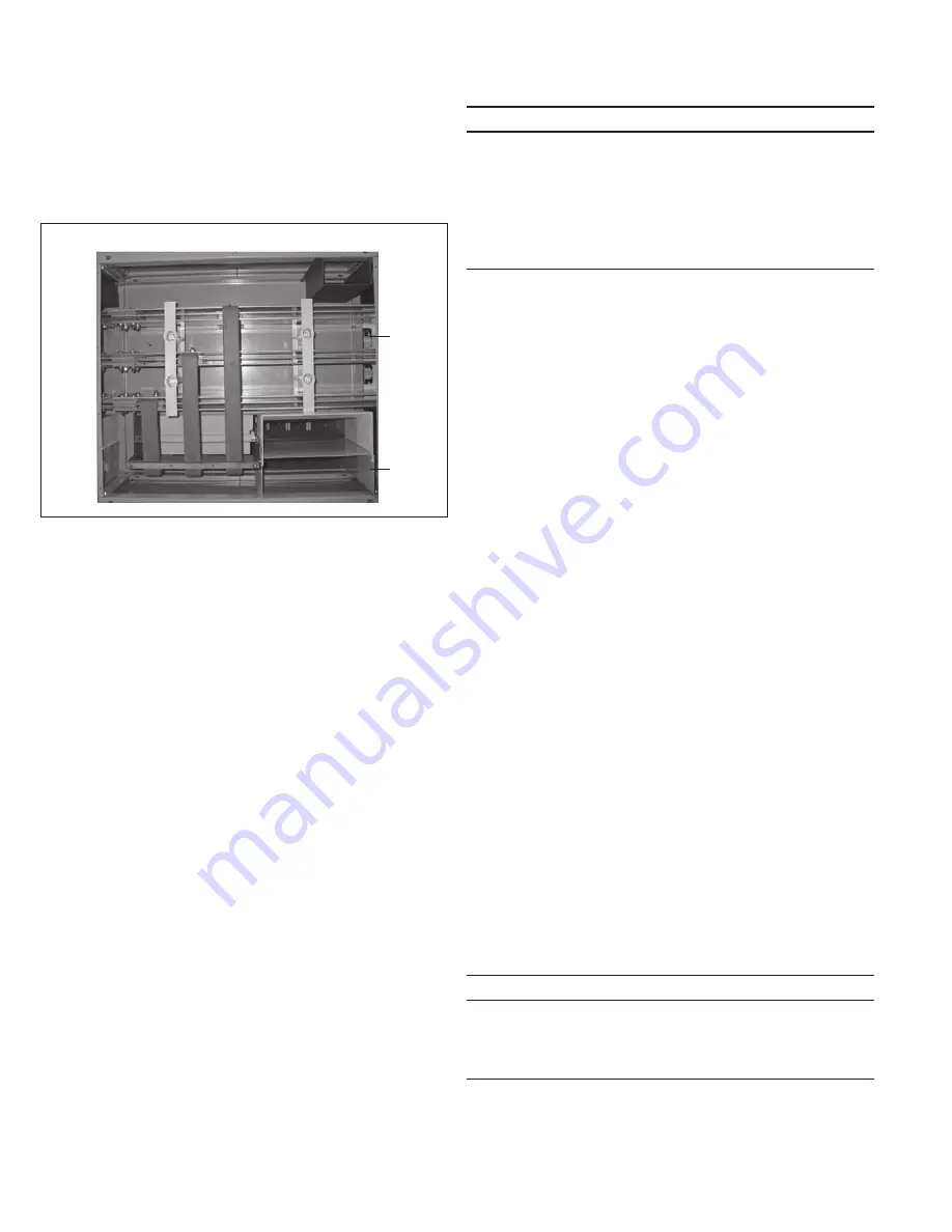
Main bus
AMPGARD lineups are typically supplied with copper main bus . The
bus is located in a 12-inch high bus compartment mounted at the top
of the lineup . Bus may be rated 1000, 1200, or 2000A . The standard
bus is insulated and tin-plated . Optional silver plating is available .
Bus specifications can be found on the job specific order drawings .
Main
Bus
Front
LV
Conduit
Space
MV
Conduit
Space
Vertical
Bus
Figure 15. Main Bus Compartment, Top View
The main bus compartment in a starter section includes vertical
bus drops to connect the starter(s) to the main bus . Also included
are wireways for routing of motor load and control cables to the
starters below .
installation
Handling
An AMPGARD controller is insulated for high voltages and must be
protected against damage during handling . The controller should
remain in an upright position at all times .
Exercise extreme care during any movement and placement
operations to prevent dropping or unintentional rolling or tipping .
AMPGARD medium voltage equipment may be moved by forklift,
rollers, or overhead crane .
A forklift is usually the most convenient method of handling the
controller . Use safety straps around the protective packaging
material when handling the controller with a forklift . Insert the forks
under the shipping skid . Do not allow the end of the forks to enter
the bottom of the enclosure .
Rod or pipe rollers provide a simple method for moving the controller
on a level floor . The bottom of the AMPGARD structure is designed
to be rolled without damage on minimum 2-inch diameter rollers,
four rollers per 36-inch section .
AMPGARD controllers are shipped with two steel lifting angles,
one in front and one in back, running the full width of the shipping
section . Back-to-back units also have one in the back and one in
the front, running the full width of the shipping section . Select or
adjust the rigging lengths to compensate for any unequal distribution
of the load, and maintain the controller in an upright position .
Some controller interiors may contain heavy equipment, such as
transformers, that can make the center of gravity vary considerably
from the center of the lineup .
Do not allow the angle between
the lifting cables and vertical to exceed 45 degrees.
Do not pass
ropes or cables through the lift holes . Use slings with safety hooks
or shackles, of adequate load rating .
m
caution
each controller is properly aDjusteD at the factory before
shipment. however, vibration anD mechanical stresses
imposeD by transit anD installation can aDversely affect
mechanical interlocks anD other aDjustments; therefore,
a final inspection is essential before energizing. if this
inspection reveals any portion of the controller has come
out of aDjustment, the controller shoulD be re-aDjusteD
accorDing to information in this instruction book or by a
qualifieD eaton service engineer.
Storage
If it is necessary to store an AMPGARD controller before installation,
keep it in a clean, dry location with ample air circulation and heat to
prevent condensation . Like all electrical apparatus, an AMPGARD
controller contains insulation that must be protected against dirt
and moisture .
Mounting
AMPGARD controllers should be installed on a non-combustible level
surface of sufficient strength to properly support the controller’s
mass . After the lineup has been placed in position, anchor bolts
may be installed and tightened . Refer to the job specific order
drawings for the bolt locations . The use of 1/2-inch diameter bolts
is recommended .
Equipment located in certain seismic zones must be anchored to
meet the requirements of those zones . Refer to Eaton I .B . 48042 for
instructions on mounting in these special locations . It is the user’s
responsibility to ensure the mounting pad is sufficiently strong to
properly anchor and support the equipment .
When an order includes two or more shipping sections, the order
outline drawing will show the sequence in which the sections are
to be lined up and which shipping splits are to be joined . A busbar
splice kit and a connecting hardware kit are supplied for each open
joint between sections .
Place the first shipping split into position . Move the second
shipping split into position alongside the first and use the six or
eight 3/8 x 1 .50 inch bolts and companion hardware to connect the
two sideplates . Place one flat washer under the bolt head and one
flat washer and one lock washer under the nut . Tighten each bolt
to 25 lb-ft (33 Nm) .
Bus splicing
Connect the busbars using the splice kit, including hardware
(3/8-inch diameter) that is provided with the equipment . Tighten
bolts to 25 lb-ft (33 Nm) .
Power connections
Incoming power connects to the lineup in a variety of ways . Cables,
bus from other close-coupled equipment, busduct, and transformer
shunts are some of the more common methods . Note that these
connections may be energized even when the starter isolation
switch or other switching devices are in the open position .
m
Danger
De-energize anD lock out all incoming power connections
at their source before servicing any part of the equipment
Directly connecteD to the incoming power incluDing main
horizontal bus, vertical bus, bus potential transformers,
or control power transformers.