


Page 40
iQ Series AiM
™
Automation in Mind
,
Ultrasonic Power Supply User’s Manual
Dukane Manual Part No. 403-610-02
iQLinQ
iQLinQ
™
communication options allow automated
systems to monitor and change settings in
iQ
generators.
These options provide machine builders the ability to
integrate the generator into an electrical cabinet and to use
the machine’s HMI to program or monitor weld settings.
All Dukane
iQ
AiM
™
generators include
iQLinQ
™
EtherNet/IP and Modbus TCP/IP communication protocol
support. Using one of these protocols avoids adding
expensive analog cards into PLC racks.
iQLinQ
™
is
available for Profibus, PowerLink, Profinet, EtherCat, and
CC-Link with the optional ANYBUS module.
iQLinQ
™
templetes are available to provide complete
ladder logic and HMI screens that can be dropped into Allen
Bradley (RSLogix 5000; Studio 5000 Logix Designer;
Factory View Studio ME), Siemens (TIA Portal), and
B&R (Automation Studio) PLC projects.
Contact your local Dukane representative for more
information about the
iQLinQ
™
options.
iQ
LinQ
™
The
iQLinQ
™
option allows the
iQ
generator to connect to
an industrial network.
Control Parameters Available via
iQLinQ
™
1. Set weld method to Time, Energy, Peak Power, Dis-
tance, and/or Position. Set associated values in seconds,
joules, watts, or millimeters/inches.
2. Set Amplitude, Ramp Up Time, and Ramp Down Time.
3. Enable and set Trigger by Power or Trigger By Position
parameters.
4. Enable and set Hold time.
5. Enable and set Afterburst delay and duration.
6. Enable checking for Suspect Parts. Set maximum and
minimum values for Time, Power, Energy, Distance,
and/or position.
7. Enable checking for Bad Parts. Set maximum and
minimum values for Time, Power, Energy, Distance,
and/or position.
8. Configure advanced hardware settings including Fre
-
quency tracking, Free Run Frequency, Frequency Lock
and Hold, and Frequency limits.
Parameters that can be obtained via
iQLinQ
™
1. All parameters that are configured via
iQLinQ
™
.
2. Real time data which includes welder state (ultrasound
active or not), frequency, power, amplitude, and posi-
tion
.
3. Weld cycle data from previous weld which includes:
• Cycle Count
• Good, Bad, and Suspect Part information
• Process Limit setting exceeded or not reached if Bad
or Suspect Part checking is enabled
• Weld Time
• Weld Energy
• Peak Power
• Weld Distance
• Weld End Position
For information on how to control and/or monitor specific pa
-
rameters,
iQ
Generator
iQLinQ
™
Communication and Control
documentation is available.
Signing a non-disclosure agreement is required to obtain this
documentation.
™
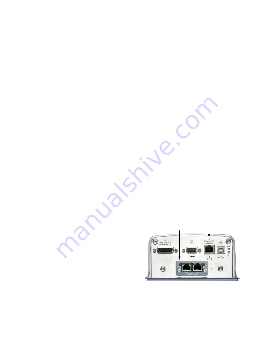
ETHERNET/IP or MODBUS TCP/IP CONNECTOR
OPTIONAL ANYBUS MODULE
Figure 4-14
J9 EtherNet/IP or Modbus Connector
J6 Optional ANYBUS Module


