background image

Operation 


057-281  ISSUE: 1 

Page 42 of 58 


5.3  EXTERNAL AC VOLTAGE BIAS 


NOTE: Voltage adjust range is configured using DSE Configuration Suite PC Software. For 

further details, refer to DSE Publication: 057-271   DSEA108 Configuration Suite PC Software 
Manual. 

 
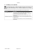
Two external bias inputs are provided to allow remote adjustment of the alternator output. 
 

Input type 

Description 

DC Voltage Level (A+, A-) 

-10 V DC to 10 V DC to provide voltage adjustment from the 

Voltage Set Point. 

The range and centre voltage are configurable 

using the DSE Configuration Suite PC Software.  
 
Typically this input is provided by external Synchroniser / Load 
Share devices. 

Potentiometer input (P1,P2) 

Ω to 5 kΩ (centre 2.5 kΩ) to provide voltage adjustment from the 

Voltage Set Point.


Typically this input is provided by a hand or automatically operated 
potentiometer. 

Содержание DSEA108

Страница 1: ...ISSUE 1 DEEP SEA ELECTRONICS PLC DSEA108 Operator Manual Document Number 057 281 Author Jack Zochling...

Страница 2: ...in accordance with the provisions of the Copyright Designs and Patents Act 1988 Applications for the copyright holder s written permission to reproduce any part of this publication should be addresse...

Страница 3: ...CONNECTOR B EXTERNAL VOLTAGE BIAS INPUT 13 3 2 TYPICAL WIRING DIAGRAMS 14 3 2 1 AUXILIARY WINDING CONNECTION 15 3 2 2 SHUNT CONNECTION 16 4 SETUP PROCEDURE 17 4 1 AVR INITIAL SETTINGS 17 4 2 FIRST STA...

Страница 4: ...1 1 1 VREP VOLTAGE REGULATOR EXCITATION STATUS 46 8 1 1 2 VROM VOLTAGE REGULATOR OPERATING MODE 46 8 1 1 3 GAAC GENERATOR AVERAGE BASIC AC QUANTITIES 46 8 1 1 4 DM1 DIAGNOSTIC MESSAGE 1 47 8 1 1 5 PRO...

Страница 5: ...served could result in damage or destruction of equipment WARNING Indicates a procedure or practice which could result in injury to personnel or loss of life if not followed correctly 1 2 GLOSSARY OF...

Страница 6: ...tallation Instructions 1 3 2 MANUALS DSE Part Description 057 238 DSEA108 Configuration Suite PC Software Manual 1 3 3 THIRD PARTY DOCUMENTS The following third party documents are also referred to Re...

Страница 7: ...ication port is for temporary use and service access only by qualified service personnel only Use appropriate Personal Protective Equipment PPE during connection as risk of potential shock hazard Must...

Страница 8: ...True RMS up to 11th harmonic Primary To Ground Resistance 4 M from each phase to A and P2 internally connected Phase to Phase Resistance 600 k between terminals L1 and N L2 Voltage 15 V AC to 600 V AC...

Страница 9: ...set using PC software DC Voltage Bias Range 1 V to 16 V of Nominal Voltage set using PC software 2 7 EXCITER FIELD OUTPUT Parameter Description Exciter Winding Impedance 5 to 50 Exciter Winding Induc...

Страница 10: ...16 Output Voltage V Output Current A Output Voltage vs Current 0 1 2 3 4 5 6 7 8 0 100 200 300 400 500 600 700 800 0 10 20 30 40 50 60 Output Current A Output Power W Exciter Resistance Exciter Power...

Страница 11: ...x 4 3 x 2 4 Mounting Type Screw Mounting to Chassis Mounting Holes Suitable for M5 bolts screws Outside diameter 5 5 mm Outside diameter 0 2 Mounting Hole Centres 149 mm x 85 mm 5 9 x 3 3 2 10 TEMPERA...

Страница 12: ...iguration refer to DSE Publication 057 283 DSEA108 Configuration Suite PC Software Manual In conjunction with the DSE815 Configuration Interface the Configuration Port is provided to give a simple mea...

Страница 13: ...r Auxiliary Winding 2 5 mm AWG13 F Connection to the positive terminal of the generator Exciter Field Winding 2 5 mm AWG13 F Connection to the negative terminal of the generator Exciter Field Winding...

Страница 14: ...d or property only qualified personnel having full understanding of the application must install the product NOTE The DSEA108 AVR is only suitable for alternators with Auxiliary Winding or Shunt conne...

Страница 15: ...Installation Page 15 of 58 057 281 ISSUE 1 3 2 1 AUXILIARY WINDING CONNECTION...

Страница 16: ...Installation 057 281 ISSUE 1 Page 16 of 58 3 2 2 SHUNT CONNECTION...

Страница 17: ...ne must be commissioned as far as possible before this procedure is carried out in particular the governor must be setup to produce stable speed control at 1500 RPM 1800 RPM Use DSE Configuration Suit...

Страница 18: ...parameter to be configured Leave the Droop and External Bias settings in their default states initially these are to be addressed later Using DSE Configuration Suite PC Software select the appropriate...

Страница 19: ...et Point to 0 Set the Maximum Duty Cycle to 100 Leave all other Excitation Output values at default Leave the Soft Start values at default for the first start If an excessive voltage spike occurs on s...

Страница 20: ...ly connected phase to neutral NOTE If an oscilloscope is not available the voltmeter and SCADA screen are used solely This does not show rapid oscillation of the voltage output and hence does not prov...

Страница 21: ...shing Corrupt configuration Write the configuration to the AVR again if this reoccurs the AVR is faulty and should be returned Single Flash Start up Failed Trip Voltage Feedback Failed to Reach 70 of...

Страница 22: ...y are consistent but not reaching the full feedback voltage then check if an Integral Limit warning is active The Integral Limit warning is viewed in either the Output Duty Cycle box on the Diagnostic...

Страница 23: ...e the Proportional setting by turning the Proportional preset clockwise until the generator output voltage becomes unstable Very slowly decrease the Proportional setting until the voltage stabilises M...

Страница 24: ...e of this process then occurs the AVR decreases the excitation output voltage to decrease generator output voltage As with the step up if the decrease is too large the set point is surpassed requiring...

Страница 25: ...ustment tool The Derivative preset can only be adjusted by changing the AVR s configuration file The settings is found on the selected Stability Configuration page To begin testing increment the Deriv...

Страница 26: ...spike at a value below the voltage Set Point is shown on start up decrease this value The settings should then be adjusted to allow for the smoothest start up in the optimum time for your application...

Страница 27: ...kVA with droop set to 10 When the load reaches 80 kW at 0 8 pf 60 kvar lagging the output voltage will fall by 10 to 207 V It is the reactive power that is measured and acted upon by the AVR Since the...

Страница 28: ...on The pre defined droop setup procedure is identical to the User Configured setup procedure in all aspects other than the Droop CT AC System and Offset Angle settings When the alternator wiring topol...

Страница 29: ...n be tested using an inductive load bank 4 3 4 EXTERNAL BIAS SETTING NOTE Proceed with External Bias Setting only after the AVR has been correctly stabilised by following the Stability Settings sectio...

Страница 30: ...y isolated from all other potentials Check the Enable check box and enter the desired control range of the pot For example with settings of Offset at 5 V and Range of set point V of 2 V this means at...

Страница 31: ...e insulated potentiometer preset adjustment tool Presets are the adjusters fitted on the AVR and may be disabled if end user adjustment is not required When enabled the range of the presets is configu...

Страница 32: ...he desired control span for the preset Write the configuration to the AVR With the generator set stopped observe the setting on the SCADA Diagnostic display and turn the preset to the desired droop se...

Страница 33: ...elects the Frequency Range Any adjustments to the presets affect the selected range To adjust the alternative range first change the DIP switch position With the generator set stopped observe the sett...

Страница 34: ...is stable Test with various step loads within the limits of the generator and check that the voltage is stable with good transient response Increase to full load and check that the alternator output r...

Страница 35: ...E For further details of module configuration refer to DSE Publication 057 271 DSEA108 Configuration Suite PC Software Manual 5 1 CONTROLS AND INDICATIONS DIP Switch 1 4 Status LED Location of Presets...

Страница 36: ...enerator or to limit kvar output when paralleling a generator with the mains supply Reactive Power is the power used to supply the capacitive and inductive elements of the load Power supplied to a loa...

Страница 37: ...quired amount typically 3 to 5 4 Ensure all generators in the system are set with exactly the same nominal voltage and droop setting For example The generator off load is producing 230 V Place the gen...

Страница 38: ...y as soon as the frequency falls below the Knee Point setting After which the rate of reduction is configurable using DSE Configuration Suite PC Software between 0 Hz and 10 Hz A typical setting to st...

Страница 39: ...ed or being reached a long time after a system disturbance such as the generator starting or a change in load levels 5 1 1 5 INTEGRAL NOTE For more detailed information on the set up procedure for Int...

Страница 40: ...5 1 2 1 DIP SWITCH 1 Function DIP Switch 1 Stability Configuration 1 Off Stability Configuration 2 On 5 1 2 2 DIP SWITCH 2 AND 3 Function DIP Switch 2 DIP Switch 3 DIP Switch 4 Main Configuration OFF...

Страница 41: ...Maximum Duty Cycle on the appropriate stability menu by 50 This may require repeating depending on the duty cycle the alternator needs Two Flashes Over Excite Trip Increase the Over Excite Trip on th...

Страница 42: ...stment of the alternator output Input type Description DC Voltage Level A A 10 V DC to 10 V DC to provide voltage adjustment from the Voltage Set Point The range and centre voltage are configurable us...

Страница 43: ...itation trip level is configured using DSE Configuration Suite PC Software For further details refer to DSE Publication 057 271 DSEA108 Configuration Suite PC Software Manual The excitation of the alt...

Страница 44: ...the generator is not running Loss of Feedback alarm Check Voltage sensing connections on L1 and N L2 terminals Startup Trip alarm Check Voltage sensing connections on L1 and N L2 terminals Unstable v...

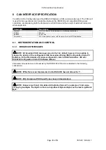
Страница 45: ...llation 8 1 INSTRUMENTATION AND CONTROL 8 1 1 BROADCAST MESSAGES NOTE All broadcast CAN messages are priority 3 by default however it is possible to change the priority of the configurable CAN message...

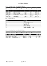
Страница 46: ...N A N A 0D30 3376 Voltage Regulator Load Compensation Mode Byte 1 Bits 4 to 6 Unimplemented N A N A 0D31 3377 Voltage Regulator Under Frequency Compensation Byte 1 Bits 7 to 8 00 UFRO Not Active 01 U...

Страница 47: ...Fault Alarm 7F002 520194 02 2 8 1 1 5 PROPB 01 AVR SETTINGS Priority Ext Data Page Data Page PDU Format PDU Specific Size Bytes Rate 3 0 0 FF 01 8 1 s SPN Hex Decimal Instrument Byte Bit Scaling Offs...

Страница 48: ...ity Selection Byte 6 N A N A N A 7F013 520211 Actual UFRO Knee Point Byte 7 to 8 0 1 Hz bit 0 Hz State Machine Status List State Description 1 Running 2 Under Frequency Roll Off Active 3 Over Excitati...

Страница 49: ...ined User Defined User Defined User Defined User Defined Configurable Value 2 Byte 5 to 8 User Defined User Defined User Defined 8 1 1 10 PROPB 33 CONFIGURABLE CAN MESSAGE 2 NOTE The Values in Configu...

Страница 50: ...A N A 8 1 2 1 VOLTAGE BIAS NOTE If no message is received by the AVR within 200 ms Voltage Bias defaults to 0 This value allows the voltage setpoint to be biased When writing to this PGN and it is de...

Страница 51: ...by writing a new value to a Data Address are held in Volatile Memory until the Store Configuration command is used to commit the changes to Non Volatile Memory Should the AVR be powered down any valu...

Страница 52: ...tore the configuration in Non Volatile Memory This ensures all changed values are retained should the DSEA108 be powered down Byte1 Byte2 Byte3 Byte4 Byte5 Byte6 Byte7 Byte8 0x03 Unused Store Configur...

Страница 53: ...t 100 to 100 R W 0 1 V 12 to 29 Reserved 30 Nominal Frequency 0 1 R W 0 50 Hz 1 60 Hz 31 UFRO Preset Enable 0 1 R W 0 Disabled 1 Enabled 32 UFRO Knee Point Must be higher than Under Frequency Trip 1 t...

Страница 54: ...s Flag List 208 DIP Switch Positions R See DIP Switch Position List 209 Software Version R Byte3 0 Byte2 Major Version Byte1 Minor Version Byte0 Build Nuber 210 Bootloader Version R Byte3 0 Byte2 Majo...

Страница 55: ...Description 0 1 Switch 1 Stability selection 2 3 Switch 2 Alternative Configuration Selection 4 5 Switch 3 Alternative Configuration Selection 6 7 Switch 4 Alternative Configuration Selection 8 to 31...

Страница 56: ...al equipment supplier OEM Connection Description Part No USB Requires DSE815 interface and connection lead 0815 01 9 1 WARRANTY DSE provides limited warranty to the equipment purchaser at the point of...

Страница 57: ...This Page is Intentionally Blank...

Страница 58: ...This Page is Intentionally Blank...

Отзывы: