Setup Procedure
Page 29 of 58
057-281 ISSUE: 1
4.3.3.3
OBTAINING AND CONFIGURING CT PHASE SHIFT
NOTE: It is very important that Droop Initial Setup procedure is followed before
continuing.
To account for the choices made for the CT, its location and which phases are used for voltage
sensing,
Offset Angle
must be configured correctly. This is performed as follows:
Start the generator set and apply a purely resistive load of at least 5% of the generator capacity, it
must
be resistive only load, with no reactive element.
Using SCADA
Frequency, Voltage and Current
, note the current lag angle. This shows the phase shift
caused by the Droop CT, its location and the AVR voltage sensing connections.
Remove the load, stop the generator and change
Offset Angle
to this noted angle and write the
configuration to the AVR.
The AVR is now compensated for the choice of phase for the CT and voltage sensing.
Droop is now set, if required it can be tested using an inductive load bank.
4.3.4 EXTERNAL BIAS SETTING
NOTE: Proceed with External Bias Setting only after the AVR has been correctly stabilised
by following the Stability Settings section first.
4.3.4.1
EXTERNAL POTENTIOMETER
NOTE: The external potentiometer is designed for manual adjustment of the output
voltage. Where automatic voltage matching or kvar sharing is required, use the DC Voltage
Input instead.
NOTE: Where both (External Potentiometer and DC Voltage Input) are used
simultaneously, both inputs are summed to determine the output voltage.
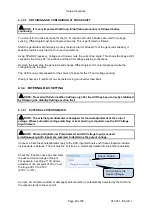
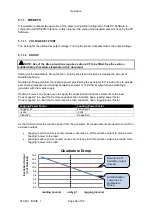
Connect a 5 k
Ω linear potentiometer (pot) to the AVR input terminals such that a clockwise rotation
increases its resistance. The pot must be
‘volt free’ i.e. electrically isolated from all other potentials.
Check the ‘Enable’ check box and enter
the desired control range of the pot.
For example, a setting of 10% allows
adjustment of a set point of 230 V over
the range 207 V to 253 V.
(230 V +/-10% )
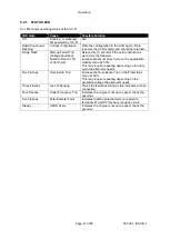
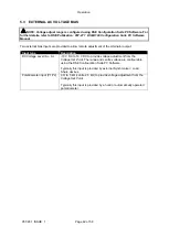
An open circuit (disconnected or damaged) potentiometer is automatically detected by the AVR and
the output returns to the set point.
‘Check’
Enable
...
and configure the
required
Range
.
Содержание DSEA108
Страница 1: ...ISSUE 1 DEEP SEA ELECTRONICS PLC DSEA108 Operator Manual Document Number 057 281 Author Jack Zochling...
Страница 15: ...Installation Page 15 of 58 057 281 ISSUE 1 3 2 1 AUXILIARY WINDING CONNECTION...
Страница 16: ...Installation 057 281 ISSUE 1 Page 16 of 58 3 2 2 SHUNT CONNECTION...
Страница 57: ...This Page is Intentionally Blank...
Страница 58: ...This Page is Intentionally Blank...


