Setup Procedure
Page 27 of 58
057-281 ISSUE: 1
4.3.3 DROOP SETTING
NOTE: Proceed with Droop setting only after the AVR has been correctly stabilised by
following the Stability Settings section first.
Quadrature Droop monitors the reactive power provided by the generator to the load and is used to
provide kvar sharing (reactive load sharing) between generators.
Droop is optional. If required, a Current Transformer (CT) must be fitted in one of the alternator
phases. The AVR must be configured correctly to match which phase the CT is fitted to, relative to the
voltage settings. This is performed in the DSE Configuration Suite PC Software.
4.3.3.1
USER CONFIGURED DROOP SETUP
Set
Droop (% of set point)
to the desired level. This is defined as the percentage by which the output
voltage will fall when the measured kvar corresponds to full load at 0.8 power factor.
For example: For a generator rated at 230 V and 100 kVA, with droop set to 10%.
When the load reaches 80 kW at 0.8 pf (60 kvar) lagging, the output voltage will fall by 10% to 207 V.
It is the
reactive
power that is measured and acted upon by the AVR.
Since there is only provision for one CT the AVR assumes that the load is balanced between the
phases.
NOTE: When completing a User Configured droop setup, it is very important that Droop
CT AC System is set to User Configured, and the Offset Angle is to 0 before proceeding.
Ensure
Droop CT AC System
is set
as
User
Configured, and Offset
Angle
is set to zero. This is the factory
default setting but must be verified
before proceeding.
Set
Full Load Current
to match the CT secondary current when the generator is at full load.
For example: For a set rated at 230 V and 100 kVA, three phase, with a 200:5 CT:
•
The full load current is (100000/230)/3 = 145 A per phase.
•
Applying the CT ratio to find the secondary current 145 x (5 /200) = 3.625 A
•
Full Load Current
should be set to 3.625 A
Write the configuration to the AVR.
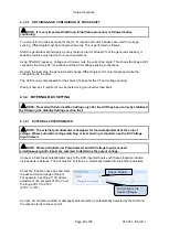
‘Uncheck’
Preset
Enable
....
and configure
Droop
Set
Droop CT AC System
to
User Configured…
And set
Offset Angle
to 0º
Содержание DSEA108
Страница 1: ...ISSUE 1 DEEP SEA ELECTRONICS PLC DSEA108 Operator Manual Document Number 057 281 Author Jack Zochling...
Страница 15: ...Installation Page 15 of 58 057 281 ISSUE 1 3 2 1 AUXILIARY WINDING CONNECTION...
Страница 16: ...Installation 057 281 ISSUE 1 Page 16 of 58 3 2 2 SHUNT CONNECTION...
Страница 57: ...This Page is Intentionally Blank...
Страница 58: ...This Page is Intentionally Blank...


