Installation Instructions for Wi-Q Technology™ EXQ Exit Hardware Trim
BEST
a Product Group of dormakaba USA Inc.
16
Installing the exit hardware and trim
14
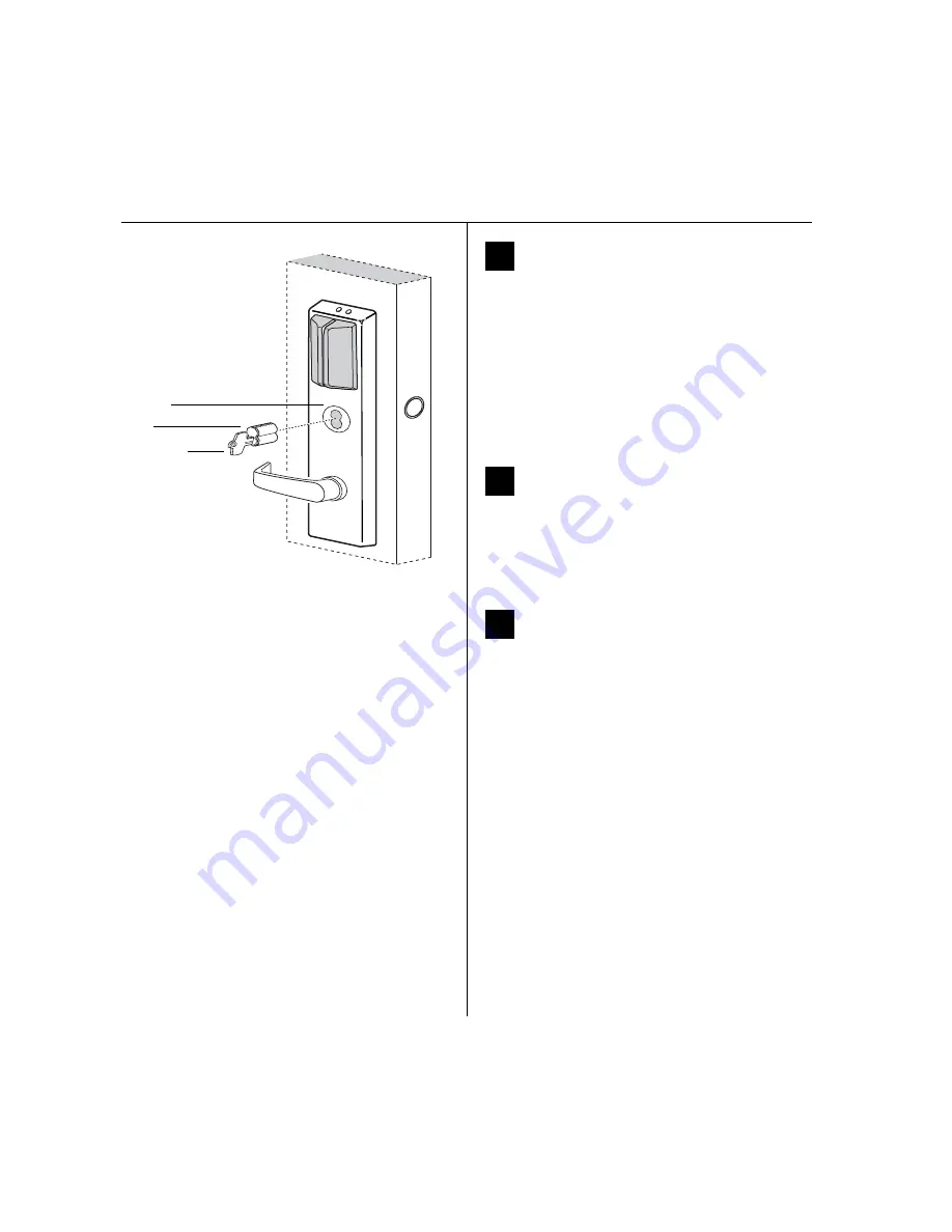
Install core
1 Insert the control key into the core and rotate the key
15 degrees to the right.
2 With the control key in the core, insert the core into
the cylinder as shown in Figure 27.
3 Rotate the control key 15 degrees to the left and with-
draw the key.
Caution:
The control key can be used to remove
cores and to access doors. Provide adequate secu-
rity for the control key.
15
Install mortise case faceplate
(mortise exit devices only)
1 Secure the mortise case faceplate to the mortise case;
follow the instructions provided by the exit hardware
manufacturer.
2 Check the lock for proper operation.
16
Install strike(s)
Note:
If retrofitting the trim to an existing exit hardware
installation, skip this task.
1 Install the strike(s) in the door frame or door stop; fol-
low the instructions provided by the exit hardware
manufacturer.
2 Check the lock for proper alignment between the
strike(s) and latch(es).
Figure 27 Installing the core
Control key
Core
Outside of door
Cylinder
Installation Instructions for Wi-Q Technology™ EXQ Exit Hardware Trim
BEST
a Product Group of dormakaba USA Inc.
15
Installation Instructions for Wi-Q Technology™ EXQ Exit Hardware Trim
Installing the exit hardware and trim
5 Make sure to route and dress the wires so that they do
not interfere with any moving parts.
6 Tape the wires to the device head (some tape is pro-
vided).
Note:
For Precision 2200, 2700, and 2800 exit devices,
use cable ties in addition to the tape, to hold wires as
shown in Figure 26.
7 Install the case cover.
Org
NC
Blue
Tan
COM
Red
Wht
Wht
Wht
Wht
Red
Blue
Touchbar
switch
EXQ Trim
Door
position
switch
NO
Yellow Not used
Figure 25 Schematic diagram for connecting Von Duprin
sensor harness wires
Butt
splices
Sensor
harness
Not used
}
NO
= Normally Open
NC
= Normally Closed
COM
= Common
TOP
Figure 26 Using cable ties to hold wires for Precision
2200, 2700, and 2800 exit devices
Use cable tie
here to secure
the sensor
harness
Sensor har-
ness coming
thru the 5/16”
hole
described in
Figure 17
Cable tie
Содержание BEST Wi-Q ONGUARD
Страница 7: ...A Glossary Glossary 109 B Lock Installation Lock Installation 113 ...
Страница 40: ...40 2 Select Inbound Rules Figure 13 Inbound Rules Select Inbound Rules ...
Страница 44: ...44 6 Select Allow the connection Click Next to continue See Figure 17 Figure 17 Allow the Connection ...
Страница 45: ...45 7 De select the Public option Click Next Figure 18 De select Public ...
Страница 52: ...52 Figure 27 Wi Q Interface Setup Wizard Click Next ...
Страница 57: ...57 Figure 33 Custom Setup Options Click Next ...
Страница 58: ...58 10 The wizard is now ready to begin installation Click Install Figure 34 Begin Installation Click Install ...
Страница 75: ...75 To add a new Sign On Credential 1 Select Add Figure 52 Add Segment Sign On Credential 1 ...
Страница 113: ...B Lock installation ...
Страница 168: ...6161 East 75th Street Indianapolis IN 46250 USA Phone 1 800 392 5209 https dhwsupport dormakaba com hc en us 172713 S3 ...


