Vehicle System
Disassembly & Assembly
57
Assemble Steering Unit
Check all mating surfaces. Replace any parts that
have scratches or burrs that could cause leakage.
Clean all metal parts in clean solvent. Blow dry with
air. Do not wipe dry with cloth or paper towel
because lint or other matter can get into the
hydraulic system and cause damage. Do not use a
coarse grit or try to file or grind these parts.
NOTE:
Lubricate all seals with clean petroleum jelly
such as Vaseline.
Do not use excessive lubricant on seals for meter
section.
Refer to parts listings covering your steering unit
when ordering replacement parts. A good service
policy is to replace all old seals with new seals.
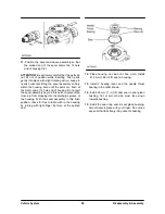
1.
Use a needle nose pliers to lower check ball
retainer into check valve hole of housing. Make
sure retainer is straight (not tilted on edge) in
housing.
2.
Install check ball in housing.
3.
Lubricate 9.3 mm [.36 in.] ID seal and 7.7 mm
[.30in.] ID seal. Install seals on check ball seat as
shown.
4.
Lubricate check ball seat and seals thoroughly
before installing seat in housing. When installing
seat do not twist or damage seals. Install check
ball seat in housing, insert open end of seat first.
Push check ball seat to shoulder of hole.
5.
Install set screw. Use a 1/4 inch hex key to torque
set screw to 11 N
•
m [100 lb
•
in]. To prevent
interference make sure top of set screw in slightly
below housing mounting surface.
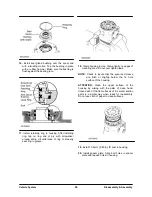
6.
Assemble spool and sleeve carefully so that the
spring slots line up at the same end. Rotate spool
while sliding parts together. Some spool and
sleeve sets have identification marks, align these
marks. Test for free rotation. Spool should rotate
smoothly in sleeve with finger tip force applied at
splined end.
7.
Bring spring slots of both parts in line and stand
parts on end of bench. Insert spring installation
tool through spring slots of both parts. Position
2pairs of centering springs on bench so that
extended edge is down and arched center section
is together. In this position, insert one end of
entire spring set into spring installation tool, with
spring notches facing sleeve.
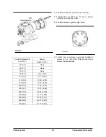
8.
Compress extended end of centering spring set
and push into spool sleeve assembly with drawing
installation tool at the same time.
9.
Center the spring set in the parts so that they
push down evenly and flush with the upper
surface of the spool and sleeve.
10.
Install pin through spool and sleeve assembly
until pin is flush at both sides of sleeve.
Содержание D20G
Страница 2: ......
Страница 5: ...Specifications TORQUE SPECIFICATIONS SB2004E00 D e c 1 9 9 8 ...
Страница 14: ......
Страница 16: ......
Страница 34: ...Diesel Engine Engine Identification 20 1 Exhaust Valve Port 2 Exhaust Manifold 00900232 Exhaust System ...
Страница 138: ...Diesel Engine Engine System 124 NOTE The crankshaft must rotate freely by hand 02900058 ...
Страница 199: ...Diesel Engine Engine System 185 Install the needle valve and nozzle assembly Install the nozzle nut fi900ce fi900ob ...
Страница 254: ......
Страница 256: ......
Страница 260: ......
Страница 334: ...4TNV98 4TNE98 Diesel Engine Section 3 Engine 80 Cylinder Head Cylinder Head Components 4TNV98 Engine Figure 6 36 ...
Страница 341: ...4TNV98 4TNE98 Diesel Engine Section 3 Engine 87 4TNE98 Engine Figure 6 1 ...
Страница 363: ...4TNV98 4TNE98 Diesel Engine Section 3 Engine 109 Crankshaft and Camshaft Components Figure 6 84 ...
Страница 423: ...4TNV98 4TNE98 Diesel Engine Section 4 Fuel System 169 Fuel System Components Figure 7 1 ...
Страница 425: ...4TNV98 4TNE98 Diesel Engine Section 4 Fuel System 171 Structure And Operation Of Fuel Injection Pump Figure 7 3 ...
Страница 468: ...4TNV98 4TNE98 Diesel Engine Section 6 Lubrication System 214 Lubrication System Diagram Figure 9 1 ...
Страница 477: ...4TNV98 4TNE98 Diesel Engine Section 7 Starter Motor 223 Starter Motor Troubleshooting ...
Страница 494: ...4TNV98 4TNE98 Diesel Engine Section 8 Troubleshooting 240 Troubleshooting Charts ...
Страница 495: ...4TNV98 4TNE98 Diesel Engine Section 8 Troubleshooting 241 ...
Страница 496: ...4TNV98 4TNE98 Diesel Engine Section 8 Troubleshooting 242 ...
Страница 498: ...4TNV98 4TNE98 Diesel Engine Section 8 Troubleshooting 244 4TNE98 Engine ...
Страница 499: ...Service Manual G424FE LP Engine G424F LP Gasoline Engine G20G G25G G30G SB4320E00 Jan 2008 ...
Страница 500: ......
Страница 502: ......
Страница 529: ...G424F FE Service Manual Chapter 2 Recommended Maintenance 29 ...
Страница 534: ...G424F FE Service Manual Chapter 3 Engine Mechanical System 34 MAIN BEARINGS 0 50 UNDERSIZE ...
Страница 584: ...G424F FE Service Manual Chapter 3 Engine Mechanical System 84 ...
Страница 611: ...G424F FE Service Manual Chapter 4 Engine Electrical System 111 2 Alternator and outer terminal connection inspection ...
Страница 649: ...G424F FE Service Manual Chapter 5 Engine Management System EMS 149 Figure 22 SECM Wiring Diagram for G424FE LP System ...
Страница 727: ...G424F FE Service Manual 227 Chapter 8 Basic Troubleshooting Irregular Idling Or Engine Is Suddenly Stopped ...
Страница 728: ...G424F FE Service Manual 228 Chapter 8 Basic Troubleshooting Engine Hesitation Or Insuffient Accelelation ...
Страница 729: ...G424F FE Service Manual 229 Chapter 8 Basic Troubleshooting ...
Страница 731: ...G424F FE Service Manual 231 Chapter 8 Basic Troubleshooting ...
Страница 806: ......
Страница 808: ......
Страница 810: ......
Страница 820: ...Power Train System Operation 14 Hydraulic System ...
Страница 822: ...Power Train System Operation 16 Hydraulic System ...
Страница 824: ...Power Train System Operation 18 Hydraulic System ...
Страница 826: ...Power Train System Operation 20 Hydraulic System ...
Страница 856: ......
Страница 858: ......
Страница 860: ......
Страница 930: ......
Страница 932: ......
Страница 934: ......
Страница 936: ......
Страница 1018: ......
Страница 1023: ...A374081 01 ELECTRIC SCHEMATIC MODEL D20 25 30G EM0K2 EM0K3 Cummins B3 3 ...
Страница 1024: ...A654030 00 ELECTRIC SCHEMATIC MODEL D20 25 30G EM0QM EM0QN Yanmar 4TNE98 Tier 3 ...
Страница 1025: ...A604500 00 ELECTRIC SCHEMATIC MODEL G20 25 30G EM0QF EM0QG GM G424F Non Certi LP ...
Страница 1026: ...A604510 00 ELECTRIC SCHEMATIC MODEL G20 25 30G EM0QH EM0QJ GM G424F Non Certi GAS ...
Страница 1027: ...A604516 00 ELECTRIC SCHEMATIC MODEL G20 25 30G EM0QY EM0QZ GM G424FE Tier 3 LP ...
Страница 1028: ......
Страница 1030: ......
Страница 1059: ...Safety Section 29 Lean away from the direction of fall Lean forward ...
Страница 1071: ...General Section 41 Typical Example Side Shifter Serial Number If Equipped ...


