


G424F(FE) Service Manual
282
Appendix
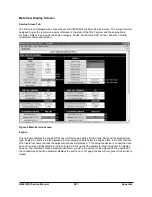
AFR (Air Fuel Ratio) Control
The AFR Control category is divided into two
separate sections, one for LP and a second for
Gasoline, (active on bi-fuel units). Key parameters
for AFR Control include the “Open-Loop”/ “Closed-
Loop” control listing. This description informs the
technician whether the emission system is using
closed loop feedback from the oxygen sensors to
control the AFR delivered to the exhaust catalyst or
using tables in the engine control module for AFR
control in open loop mode.
Both the pre catalyst (pre-CAT) and post catalyst
(post-CAT) oxygen sensor setpoint values are
displayed in Phi along with adaptive learn values.
When in LP mode the FTV (Fuel Trim Valves) duty
cycle is displayed in percent. If the system is running
rich in closed loop, the duty cycle will increase to
lean out the LP mixture to the engine. When in
Gasoline operation the average fuel injector pulse
width is displayed along with each individual fuel
injector signal. Oxygen sensor values have been
converted to voltage for easier troubleshooting using
a multi-meter.
Faults
A brief fault list is displayed in the Fault category.
Active faults display the description of all active
faults—faults that are actively taking place when
connected to the SECM. Occurred faults display the
description of all stored faults. The first five stored
faults of the ten possible fault stored record are
displayed by the three digit fault codes. Definitions
of these fault codes can be located on the DFC
screens.
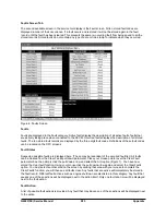
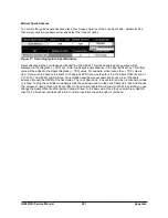
Fault States
Suspected possible faults are displayed here.
(These may be redundant of the occurred fault list.)
All faults can be cleared from the Clear Faults pull
down parameter. Place your mouse pointer over the
Clear Fault parameter box, then simply click the pull
down arrow and select the Arm option. You have
now armed the clear fault function. Using your
mouse click the pull down arrow again and select
the ClearFaults option. You must select another
area on the screen by clicking that area with your
mouse to complete the Clear Faults function; you
will then see all faults clear. Any faults that are
active will immediately be stored in the fault record.
Different fault actions such as engine shutdown are
also listed in this category. Any fault that causes one
of these actions will be displayed next to the action
itself. Only one fault at a time will be displayed next
to the fault action.
Figure 7 Clearing Faults
Sensors
Key sensor values are displayed in this category.
ECT (Engine Coolant Temperature) will turn green
when the correct engine operating temperature is
reached (75°C [167°F]).
Throttle
The throttle category displays the throttle setpoint,
which is the value the SECM is trying to control the
throttle to. TPS (Throttle Position Sensor) 1 & 2
values are also displayed in percent.
Accelerator Pedal
APP (Accelerator Pedal Position sensor) 1&2 values
are displayed in percent.
Содержание D20G
Страница 2: ......
Страница 5: ...Specifications TORQUE SPECIFICATIONS SB2004E00 D e c 1 9 9 8 ...
Страница 14: ......
Страница 16: ......
Страница 34: ...Diesel Engine Engine Identification 20 1 Exhaust Valve Port 2 Exhaust Manifold 00900232 Exhaust System ...
Страница 138: ...Diesel Engine Engine System 124 NOTE The crankshaft must rotate freely by hand 02900058 ...
Страница 199: ...Diesel Engine Engine System 185 Install the needle valve and nozzle assembly Install the nozzle nut fi900ce fi900ob ...
Страница 254: ......
Страница 256: ......
Страница 260: ......
Страница 334: ...4TNV98 4TNE98 Diesel Engine Section 3 Engine 80 Cylinder Head Cylinder Head Components 4TNV98 Engine Figure 6 36 ...
Страница 341: ...4TNV98 4TNE98 Diesel Engine Section 3 Engine 87 4TNE98 Engine Figure 6 1 ...
Страница 363: ...4TNV98 4TNE98 Diesel Engine Section 3 Engine 109 Crankshaft and Camshaft Components Figure 6 84 ...
Страница 423: ...4TNV98 4TNE98 Diesel Engine Section 4 Fuel System 169 Fuel System Components Figure 7 1 ...
Страница 425: ...4TNV98 4TNE98 Diesel Engine Section 4 Fuel System 171 Structure And Operation Of Fuel Injection Pump Figure 7 3 ...
Страница 468: ...4TNV98 4TNE98 Diesel Engine Section 6 Lubrication System 214 Lubrication System Diagram Figure 9 1 ...
Страница 477: ...4TNV98 4TNE98 Diesel Engine Section 7 Starter Motor 223 Starter Motor Troubleshooting ...
Страница 494: ...4TNV98 4TNE98 Diesel Engine Section 8 Troubleshooting 240 Troubleshooting Charts ...
Страница 495: ...4TNV98 4TNE98 Diesel Engine Section 8 Troubleshooting 241 ...
Страница 496: ...4TNV98 4TNE98 Diesel Engine Section 8 Troubleshooting 242 ...
Страница 498: ...4TNV98 4TNE98 Diesel Engine Section 8 Troubleshooting 244 4TNE98 Engine ...
Страница 499: ...Service Manual G424FE LP Engine G424F LP Gasoline Engine G20G G25G G30G SB4320E00 Jan 2008 ...
Страница 500: ......
Страница 502: ......
Страница 529: ...G424F FE Service Manual Chapter 2 Recommended Maintenance 29 ...
Страница 534: ...G424F FE Service Manual Chapter 3 Engine Mechanical System 34 MAIN BEARINGS 0 50 UNDERSIZE ...
Страница 584: ...G424F FE Service Manual Chapter 3 Engine Mechanical System 84 ...
Страница 611: ...G424F FE Service Manual Chapter 4 Engine Electrical System 111 2 Alternator and outer terminal connection inspection ...
Страница 649: ...G424F FE Service Manual Chapter 5 Engine Management System EMS 149 Figure 22 SECM Wiring Diagram for G424FE LP System ...
Страница 727: ...G424F FE Service Manual 227 Chapter 8 Basic Troubleshooting Irregular Idling Or Engine Is Suddenly Stopped ...
Страница 728: ...G424F FE Service Manual 228 Chapter 8 Basic Troubleshooting Engine Hesitation Or Insuffient Accelelation ...
Страница 729: ...G424F FE Service Manual 229 Chapter 8 Basic Troubleshooting ...
Страница 731: ...G424F FE Service Manual 231 Chapter 8 Basic Troubleshooting ...
Страница 806: ......
Страница 808: ......
Страница 810: ......
Страница 820: ...Power Train System Operation 14 Hydraulic System ...
Страница 822: ...Power Train System Operation 16 Hydraulic System ...
Страница 824: ...Power Train System Operation 18 Hydraulic System ...
Страница 826: ...Power Train System Operation 20 Hydraulic System ...
Страница 856: ......
Страница 858: ......
Страница 860: ......
Страница 930: ......
Страница 932: ......
Страница 934: ......
Страница 936: ......
Страница 1018: ......
Страница 1023: ...A374081 01 ELECTRIC SCHEMATIC MODEL D20 25 30G EM0K2 EM0K3 Cummins B3 3 ...
Страница 1024: ...A654030 00 ELECTRIC SCHEMATIC MODEL D20 25 30G EM0QM EM0QN Yanmar 4TNE98 Tier 3 ...
Страница 1025: ...A604500 00 ELECTRIC SCHEMATIC MODEL G20 25 30G EM0QF EM0QG GM G424F Non Certi LP ...
Страница 1026: ...A604510 00 ELECTRIC SCHEMATIC MODEL G20 25 30G EM0QH EM0QJ GM G424F Non Certi GAS ...
Страница 1027: ...A604516 00 ELECTRIC SCHEMATIC MODEL G20 25 30G EM0QY EM0QZ GM G424FE Tier 3 LP ...
Страница 1028: ......
Страница 1030: ......
Страница 1059: ...Safety Section 29 Lean away from the direction of fall Lean forward ...
Страница 1071: ...General Section 41 Typical Example Side Shifter Serial Number If Equipped ...


