4TNV98 & 4TNE98 Diesel Engine
Section 2. Periodic Maintenance
43
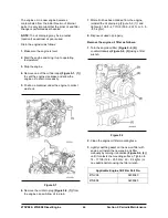
Periodic Maintenance Procedures
Daily
Perform the following procedures daily.
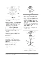
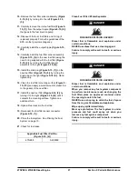
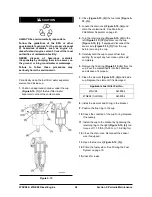
• Drain Fuel Filter / Water Separator
• Check Fuel Hoses and Engine Coolant Hoses
Drain Fuel Filter / Water Separator
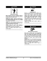
DANGER
FIRE AND EXPLOSION HAZARD!
•
Diesel fuel is extremely flammable and
explosive under certain conditions.
• When you remove any fuel system component
to perform maintenance (such as changing the
fuel filter) place an approved container under
the opening to catch the fuel.
• NEVER use a shop rag to catch the fuel. Vapors
from the rag are extremely flammable and
explosive.
• Wipe up any spills immediately.
• Wear eye protection. The fuel system is under
pressure and fuel could spray out when you
remove any fuel system component.
• Failure to comply will result in death or serious
injury.
0000009en.
4TNE98 For D25S-5 Only
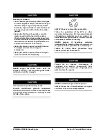
WARNING
HIGH PRESSURE HAZARD!
•
Avoid skin contact with high pressure diesel
fuel spray caused by a fuel system leak such as
a broken fuel injection line. High pressure fuel
can penetrate your skin and result in serious
injury. If you are exposed to high pressure fuel
spray obtain prompt medical treatment.
• NEVER check for a fuel leak with your hands.
ALWAYS use a piece of wood or cardboard.
Have your authorized Yanmar industrial engine
dealer or distributor repair the damage.
• Failure to comply could result in death or
serious injury.
0000008en.
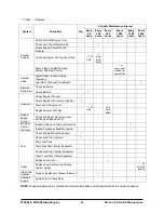
CAUTION
If no water drips when the fuel filter/water
separator drain cock is opened, loosen the air
vent screw on the top of the fuel filter/water
separator by using a screwdriver to turn it
counterclockwise 2-3 turns.This may occur if the
fuel filter / water separator is positioned higher
than the fuel level in the fuel tank. After draining
the fuel filter/water separator, be sure to tighten
the air vent screw.
0000025en
.
Содержание D20G
Страница 2: ......
Страница 5: ...Specifications TORQUE SPECIFICATIONS SB2004E00 D e c 1 9 9 8 ...
Страница 14: ......
Страница 16: ......
Страница 34: ...Diesel Engine Engine Identification 20 1 Exhaust Valve Port 2 Exhaust Manifold 00900232 Exhaust System ...
Страница 138: ...Diesel Engine Engine System 124 NOTE The crankshaft must rotate freely by hand 02900058 ...
Страница 199: ...Diesel Engine Engine System 185 Install the needle valve and nozzle assembly Install the nozzle nut fi900ce fi900ob ...
Страница 254: ......
Страница 256: ......
Страница 260: ......
Страница 334: ...4TNV98 4TNE98 Diesel Engine Section 3 Engine 80 Cylinder Head Cylinder Head Components 4TNV98 Engine Figure 6 36 ...
Страница 341: ...4TNV98 4TNE98 Diesel Engine Section 3 Engine 87 4TNE98 Engine Figure 6 1 ...
Страница 363: ...4TNV98 4TNE98 Diesel Engine Section 3 Engine 109 Crankshaft and Camshaft Components Figure 6 84 ...
Страница 423: ...4TNV98 4TNE98 Diesel Engine Section 4 Fuel System 169 Fuel System Components Figure 7 1 ...
Страница 425: ...4TNV98 4TNE98 Diesel Engine Section 4 Fuel System 171 Structure And Operation Of Fuel Injection Pump Figure 7 3 ...
Страница 468: ...4TNV98 4TNE98 Diesel Engine Section 6 Lubrication System 214 Lubrication System Diagram Figure 9 1 ...
Страница 477: ...4TNV98 4TNE98 Diesel Engine Section 7 Starter Motor 223 Starter Motor Troubleshooting ...
Страница 494: ...4TNV98 4TNE98 Diesel Engine Section 8 Troubleshooting 240 Troubleshooting Charts ...
Страница 495: ...4TNV98 4TNE98 Diesel Engine Section 8 Troubleshooting 241 ...
Страница 496: ...4TNV98 4TNE98 Diesel Engine Section 8 Troubleshooting 242 ...
Страница 498: ...4TNV98 4TNE98 Diesel Engine Section 8 Troubleshooting 244 4TNE98 Engine ...
Страница 499: ...Service Manual G424FE LP Engine G424F LP Gasoline Engine G20G G25G G30G SB4320E00 Jan 2008 ...
Страница 500: ......
Страница 502: ......
Страница 529: ...G424F FE Service Manual Chapter 2 Recommended Maintenance 29 ...
Страница 534: ...G424F FE Service Manual Chapter 3 Engine Mechanical System 34 MAIN BEARINGS 0 50 UNDERSIZE ...
Страница 584: ...G424F FE Service Manual Chapter 3 Engine Mechanical System 84 ...
Страница 611: ...G424F FE Service Manual Chapter 4 Engine Electrical System 111 2 Alternator and outer terminal connection inspection ...
Страница 649: ...G424F FE Service Manual Chapter 5 Engine Management System EMS 149 Figure 22 SECM Wiring Diagram for G424FE LP System ...
Страница 727: ...G424F FE Service Manual 227 Chapter 8 Basic Troubleshooting Irregular Idling Or Engine Is Suddenly Stopped ...
Страница 728: ...G424F FE Service Manual 228 Chapter 8 Basic Troubleshooting Engine Hesitation Or Insuffient Accelelation ...
Страница 729: ...G424F FE Service Manual 229 Chapter 8 Basic Troubleshooting ...
Страница 731: ...G424F FE Service Manual 231 Chapter 8 Basic Troubleshooting ...
Страница 806: ......
Страница 808: ......
Страница 810: ......
Страница 820: ...Power Train System Operation 14 Hydraulic System ...
Страница 822: ...Power Train System Operation 16 Hydraulic System ...
Страница 824: ...Power Train System Operation 18 Hydraulic System ...
Страница 826: ...Power Train System Operation 20 Hydraulic System ...
Страница 856: ......
Страница 858: ......
Страница 860: ......
Страница 930: ......
Страница 932: ......
Страница 934: ......
Страница 936: ......
Страница 1018: ......
Страница 1023: ...A374081 01 ELECTRIC SCHEMATIC MODEL D20 25 30G EM0K2 EM0K3 Cummins B3 3 ...
Страница 1024: ...A654030 00 ELECTRIC SCHEMATIC MODEL D20 25 30G EM0QM EM0QN Yanmar 4TNE98 Tier 3 ...
Страница 1025: ...A604500 00 ELECTRIC SCHEMATIC MODEL G20 25 30G EM0QF EM0QG GM G424F Non Certi LP ...
Страница 1026: ...A604510 00 ELECTRIC SCHEMATIC MODEL G20 25 30G EM0QH EM0QJ GM G424F Non Certi GAS ...
Страница 1027: ...A604516 00 ELECTRIC SCHEMATIC MODEL G20 25 30G EM0QY EM0QZ GM G424FE Tier 3 LP ...
Страница 1028: ......
Страница 1030: ......
Страница 1059: ...Safety Section 29 Lean away from the direction of fall Lean forward ...
Страница 1071: ...General Section 41 Typical Example Side Shifter Serial Number If Equipped ...


