


Diesel Engine Complete Engine
77
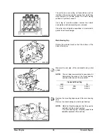
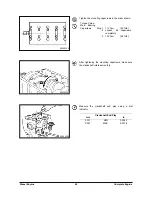
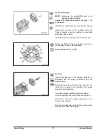
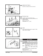
Fly Wheel Housing
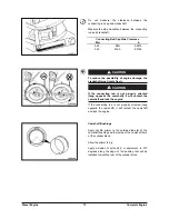
NOTE:
Make sure the crankshaft oil seal is not
damaged during installation.
Lubricate the crankshaft oil seal with Lubriplate™ 105,
or equivalent.
Install the crankshaft oil seal into the flywheel housing.
Inspect the rear face of the cylinder block and
flywheel housing mounting surface for cleanliness
and raised nicks or burrs.
Install the flywheel housing over the two dowel pins.
Tighten the flywheel housing mounting capscrews in
the sequence shown in the illustration.
Torque Value: 69 N•m [51ft-lb]
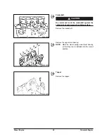
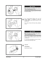
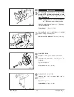
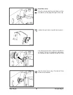
Flywheel
Install the guide pins, Part Number 3376696, or
equivalent, into the empty capscrew holes 180
degrees apart.
Determine the capscrew thread design and size, and
install two T-handles in the flywheel 180 degrees
apart on a horizontal plane.
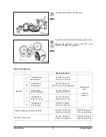
Install the coupling, retaining plate, and flywheel.
Coat all capscrews with clean lubricating engine oil.
Install four of the six mounting capscrews into the
flywheel. Hand tighten.
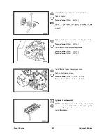
Remove the guide pins and install the remaining two
mounting capscrews. Hand tighten.
16900118
00900187
00900188
Содержание D20G
Страница 2: ......
Страница 5: ...Specifications TORQUE SPECIFICATIONS SB2004E00 D e c 1 9 9 8 ...
Страница 14: ......
Страница 16: ......
Страница 34: ...Diesel Engine Engine Identification 20 1 Exhaust Valve Port 2 Exhaust Manifold 00900232 Exhaust System ...
Страница 138: ...Diesel Engine Engine System 124 NOTE The crankshaft must rotate freely by hand 02900058 ...
Страница 199: ...Diesel Engine Engine System 185 Install the needle valve and nozzle assembly Install the nozzle nut fi900ce fi900ob ...
Страница 254: ......
Страница 256: ......
Страница 260: ......
Страница 334: ...4TNV98 4TNE98 Diesel Engine Section 3 Engine 80 Cylinder Head Cylinder Head Components 4TNV98 Engine Figure 6 36 ...
Страница 341: ...4TNV98 4TNE98 Diesel Engine Section 3 Engine 87 4TNE98 Engine Figure 6 1 ...
Страница 363: ...4TNV98 4TNE98 Diesel Engine Section 3 Engine 109 Crankshaft and Camshaft Components Figure 6 84 ...
Страница 423: ...4TNV98 4TNE98 Diesel Engine Section 4 Fuel System 169 Fuel System Components Figure 7 1 ...
Страница 425: ...4TNV98 4TNE98 Diesel Engine Section 4 Fuel System 171 Structure And Operation Of Fuel Injection Pump Figure 7 3 ...
Страница 468: ...4TNV98 4TNE98 Diesel Engine Section 6 Lubrication System 214 Lubrication System Diagram Figure 9 1 ...
Страница 477: ...4TNV98 4TNE98 Diesel Engine Section 7 Starter Motor 223 Starter Motor Troubleshooting ...
Страница 494: ...4TNV98 4TNE98 Diesel Engine Section 8 Troubleshooting 240 Troubleshooting Charts ...
Страница 495: ...4TNV98 4TNE98 Diesel Engine Section 8 Troubleshooting 241 ...
Страница 496: ...4TNV98 4TNE98 Diesel Engine Section 8 Troubleshooting 242 ...
Страница 498: ...4TNV98 4TNE98 Diesel Engine Section 8 Troubleshooting 244 4TNE98 Engine ...
Страница 499: ...Service Manual G424FE LP Engine G424F LP Gasoline Engine G20G G25G G30G SB4320E00 Jan 2008 ...
Страница 500: ......
Страница 502: ......
Страница 529: ...G424F FE Service Manual Chapter 2 Recommended Maintenance 29 ...
Страница 534: ...G424F FE Service Manual Chapter 3 Engine Mechanical System 34 MAIN BEARINGS 0 50 UNDERSIZE ...
Страница 584: ...G424F FE Service Manual Chapter 3 Engine Mechanical System 84 ...
Страница 611: ...G424F FE Service Manual Chapter 4 Engine Electrical System 111 2 Alternator and outer terminal connection inspection ...
Страница 649: ...G424F FE Service Manual Chapter 5 Engine Management System EMS 149 Figure 22 SECM Wiring Diagram for G424FE LP System ...
Страница 727: ...G424F FE Service Manual 227 Chapter 8 Basic Troubleshooting Irregular Idling Or Engine Is Suddenly Stopped ...
Страница 728: ...G424F FE Service Manual 228 Chapter 8 Basic Troubleshooting Engine Hesitation Or Insuffient Accelelation ...
Страница 729: ...G424F FE Service Manual 229 Chapter 8 Basic Troubleshooting ...
Страница 731: ...G424F FE Service Manual 231 Chapter 8 Basic Troubleshooting ...
Страница 806: ......
Страница 808: ......
Страница 810: ......
Страница 820: ...Power Train System Operation 14 Hydraulic System ...
Страница 822: ...Power Train System Operation 16 Hydraulic System ...
Страница 824: ...Power Train System Operation 18 Hydraulic System ...
Страница 826: ...Power Train System Operation 20 Hydraulic System ...
Страница 856: ......
Страница 858: ......
Страница 860: ......
Страница 930: ......
Страница 932: ......
Страница 934: ......
Страница 936: ......
Страница 1018: ......
Страница 1023: ...A374081 01 ELECTRIC SCHEMATIC MODEL D20 25 30G EM0K2 EM0K3 Cummins B3 3 ...
Страница 1024: ...A654030 00 ELECTRIC SCHEMATIC MODEL D20 25 30G EM0QM EM0QN Yanmar 4TNE98 Tier 3 ...
Страница 1025: ...A604500 00 ELECTRIC SCHEMATIC MODEL G20 25 30G EM0QF EM0QG GM G424F Non Certi LP ...
Страница 1026: ...A604510 00 ELECTRIC SCHEMATIC MODEL G20 25 30G EM0QH EM0QJ GM G424F Non Certi GAS ...
Страница 1027: ...A604516 00 ELECTRIC SCHEMATIC MODEL G20 25 30G EM0QY EM0QZ GM G424FE Tier 3 LP ...
Страница 1028: ......
Страница 1030: ......
Страница 1059: ...Safety Section 29 Lean away from the direction of fall Lean forward ...
Страница 1071: ...General Section 41 Typical Example Side Shifter Serial Number If Equipped ...


