


4TNV98 & 4TNE98 Diesel Engine
Section 5. Cooling System
207
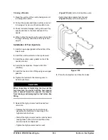
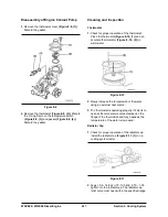
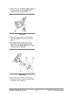
Disassembly of Engine Coolant Pump
1.
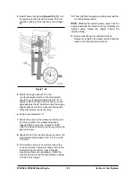
Remove the thermostat cover
(Figure 8-8, (1))
.
Discard the gasket.
Figure 8-8
2.
Remove the thermostat
(Figure 8-8, (2))
. Discard
the O-ring. Remove the temperature switch
(Figure 8-8, (3))
and gasket
(Figure 8-8, (4))
.
Discard the gasket.
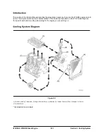
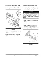
Cleaning and Inspection
Thermostat
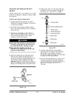
1.
Check for proper operation of the thermostat.
Place the thermostat
(Figure 8-10, (1))
and an
accurate thermometer
(Figure 8 -10, (2))
in
warm water.
Figure 8-10
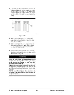
2.
Slowly increase the temperature of the water
using an external heat source.
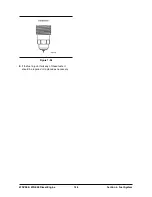
3.
The thermostat is operating properly if it starts to
open at the temperature value stamped on the
flange of the thermostat, and fully opens as the
temperature of the water is increased.
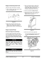
Radiator Cap
1.
Check for proper operation of the radiator cap.
Install the radiator cap
(Figure 8-11, (1))
on a
cooling system tester.
Figure 8-11
2.
Apply 10.8 - 14.8 psi (75 - 105 kPa; 0.75 - 1.05
kgf/cm²) to the radiator cap. The radiator cap
relief valve must open within the specified range.
Содержание D20G
Страница 2: ......
Страница 5: ...Specifications TORQUE SPECIFICATIONS SB2004E00 D e c 1 9 9 8 ...
Страница 14: ......
Страница 16: ......
Страница 34: ...Diesel Engine Engine Identification 20 1 Exhaust Valve Port 2 Exhaust Manifold 00900232 Exhaust System ...
Страница 138: ...Diesel Engine Engine System 124 NOTE The crankshaft must rotate freely by hand 02900058 ...
Страница 199: ...Diesel Engine Engine System 185 Install the needle valve and nozzle assembly Install the nozzle nut fi900ce fi900ob ...
Страница 254: ......
Страница 256: ......
Страница 260: ......
Страница 334: ...4TNV98 4TNE98 Diesel Engine Section 3 Engine 80 Cylinder Head Cylinder Head Components 4TNV98 Engine Figure 6 36 ...
Страница 341: ...4TNV98 4TNE98 Diesel Engine Section 3 Engine 87 4TNE98 Engine Figure 6 1 ...
Страница 363: ...4TNV98 4TNE98 Diesel Engine Section 3 Engine 109 Crankshaft and Camshaft Components Figure 6 84 ...
Страница 423: ...4TNV98 4TNE98 Diesel Engine Section 4 Fuel System 169 Fuel System Components Figure 7 1 ...
Страница 425: ...4TNV98 4TNE98 Diesel Engine Section 4 Fuel System 171 Structure And Operation Of Fuel Injection Pump Figure 7 3 ...
Страница 468: ...4TNV98 4TNE98 Diesel Engine Section 6 Lubrication System 214 Lubrication System Diagram Figure 9 1 ...
Страница 477: ...4TNV98 4TNE98 Diesel Engine Section 7 Starter Motor 223 Starter Motor Troubleshooting ...
Страница 494: ...4TNV98 4TNE98 Diesel Engine Section 8 Troubleshooting 240 Troubleshooting Charts ...
Страница 495: ...4TNV98 4TNE98 Diesel Engine Section 8 Troubleshooting 241 ...
Страница 496: ...4TNV98 4TNE98 Diesel Engine Section 8 Troubleshooting 242 ...
Страница 498: ...4TNV98 4TNE98 Diesel Engine Section 8 Troubleshooting 244 4TNE98 Engine ...
Страница 499: ...Service Manual G424FE LP Engine G424F LP Gasoline Engine G20G G25G G30G SB4320E00 Jan 2008 ...
Страница 500: ......
Страница 502: ......
Страница 529: ...G424F FE Service Manual Chapter 2 Recommended Maintenance 29 ...
Страница 534: ...G424F FE Service Manual Chapter 3 Engine Mechanical System 34 MAIN BEARINGS 0 50 UNDERSIZE ...
Страница 584: ...G424F FE Service Manual Chapter 3 Engine Mechanical System 84 ...
Страница 611: ...G424F FE Service Manual Chapter 4 Engine Electrical System 111 2 Alternator and outer terminal connection inspection ...
Страница 649: ...G424F FE Service Manual Chapter 5 Engine Management System EMS 149 Figure 22 SECM Wiring Diagram for G424FE LP System ...
Страница 727: ...G424F FE Service Manual 227 Chapter 8 Basic Troubleshooting Irregular Idling Or Engine Is Suddenly Stopped ...
Страница 728: ...G424F FE Service Manual 228 Chapter 8 Basic Troubleshooting Engine Hesitation Or Insuffient Accelelation ...
Страница 729: ...G424F FE Service Manual 229 Chapter 8 Basic Troubleshooting ...
Страница 731: ...G424F FE Service Manual 231 Chapter 8 Basic Troubleshooting ...
Страница 806: ......
Страница 808: ......
Страница 810: ......
Страница 820: ...Power Train System Operation 14 Hydraulic System ...
Страница 822: ...Power Train System Operation 16 Hydraulic System ...
Страница 824: ...Power Train System Operation 18 Hydraulic System ...
Страница 826: ...Power Train System Operation 20 Hydraulic System ...
Страница 856: ......
Страница 858: ......
Страница 860: ......
Страница 930: ......
Страница 932: ......
Страница 934: ......
Страница 936: ......
Страница 1018: ......
Страница 1023: ...A374081 01 ELECTRIC SCHEMATIC MODEL D20 25 30G EM0K2 EM0K3 Cummins B3 3 ...
Страница 1024: ...A654030 00 ELECTRIC SCHEMATIC MODEL D20 25 30G EM0QM EM0QN Yanmar 4TNE98 Tier 3 ...
Страница 1025: ...A604500 00 ELECTRIC SCHEMATIC MODEL G20 25 30G EM0QF EM0QG GM G424F Non Certi LP ...
Страница 1026: ...A604510 00 ELECTRIC SCHEMATIC MODEL G20 25 30G EM0QH EM0QJ GM G424F Non Certi GAS ...
Страница 1027: ...A604516 00 ELECTRIC SCHEMATIC MODEL G20 25 30G EM0QY EM0QZ GM G424FE Tier 3 LP ...
Страница 1028: ......
Страница 1030: ......
Страница 1059: ...Safety Section 29 Lean away from the direction of fall Lean forward ...
Страница 1071: ...General Section 41 Typical Example Side Shifter Serial Number If Equipped ...