36
BAND DRIVE GEARBOX
1.
Gearbox replacement, repair, adjustment or
alignment should be performed only by a DoALL
service representative.
2.
The machine’s gearbox reservoir capacity depends
on machine model. Check the reservoir oil daily by
referring to the side gauge.
3.
Before changing the gearbox oil, lower the saw
head completely and stop the hydraulics: (a) place
a container under the gearbox; (b) remove the
reservoir drain plug; (c) allow the reservoir to drain
completely; (d) remove the tube breather at the top
of the gearbox; (e) replace the drain plug making
sure it is tight and sealed.
4.
Fill the gearbox with oil through the tube breather
opening until it is above the
red
line on the side
gauge.
5.
Change the oil after the first three months of
operation and then every six months thereafter.
MACHINE CLEANING
1.
Keep the machine and its part as clean as possible
to prevent excessive wear or damage.
2.
Use the flushing hose as soon as possible to remove
metal chips and other waste materials which may
collect around the saw guides, band wheels, vises,
slides, sensing arm, etc. The hose has a hand
operated valve and attaches to the coolant pump
The DoALL Company recommends using the
flushing hose to remove chips at least twice per 8‐
hour shift, and more often with heavier use.
3.
Use a shovel, scoop or rake to remove accumulated
metal chips or other waste materials from the
machine areas.
Be sure the band drive motor is
stopped before cleaning
.
MACHINE ALIGNMENT
1.
Misalignment of the machine’s saw guide arms,
slide bar, saw band, pivot points, gearbox, etc. will
cause inaccurate sawing.
DO NOT attempt any alignment procedures
not covered by this manual. Contact a
DoALL service representative in such case
because special fixtures and techniques may be
required.
BAND BRUSH
1.
The band chip brush will wear and lose steel bristles
over time. Check often to be sure the bristles are
removing metal chips from the tooth tips, but are
not touching the bottom of the gullets.
2.
Move the brush closer to the blade as normal wear
occurs. Replace the brushes when necessary.
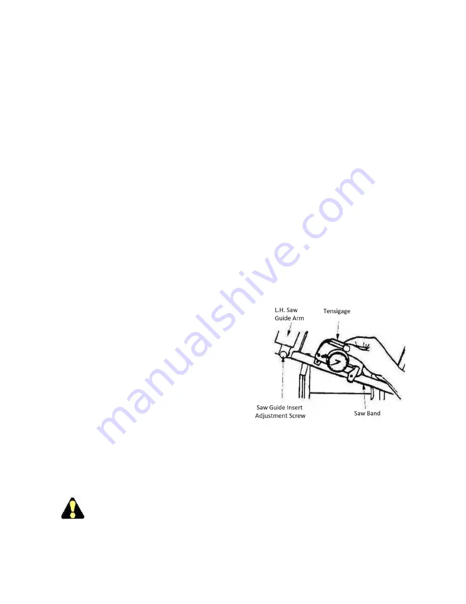
BAND TENSION MEASUREMENT
1.
Band tension is factory set.
Band tension measurement can be made with
the hydraulics running and by using a DoALL
Tensigage.
2.
Tension may be checked “reading up” or “reading
down”. To read up: (a) fix the tensigage to a slack
saw band; (b) apply tension. To read down: (a) fix
the tensigage to a tensioned saw band; (b) relax
tension.
3.
A correct DoALL tensigage reading depends on the
machine model. See the machine specification
chart.
Using a Tensigage to measure band tension.
WEAR PLATE REPLACEMENT
1.
The removable vise jaw and vise guide bars must be
replaced before excessive wear causes the
mounting screw heads to become damaged and
makes removal difficult.
Содержание C-3028NC Boxed
Страница 2: ......
Страница 3: ......
Страница 11: ...6 MACHINE DIMENSIONS Continued C 3028NC DIMENSIONS...
Страница 12: ...7 MACHINE DIMENSIONS Continued C 3028NC Boxed DIMENSIONS...
Страница 13: ...8 MACHINE DIMENSIONS Continued C 4033NC DIMENSIONS...
Страница 14: ...9 MACHINE DIMENSIONS Continued C 420NC DIMENSIONS...
Страница 15: ...10 MACHINE DIMENSIONS Continued C 420NC BOXED DIMENSIONS...
Страница 16: ...11 MACHINE DIMENSIONS Continued C 5650NC DIMENSIONS...
Страница 17: ...12 MACHINE DIMENSIONS Continued C 560NC DIMENSIONS...
Страница 18: ...13 MACHINE DIMENSIONS Continued C 6260NC DIMENSIONS...
Страница 19: ...14 MACHINE FEATURES...
Страница 39: ...34 LUBRICATION DIAGRAM...


