


ALL ABOUT IMAGE RECOGNITION & PROCESSING
ALL ABOUT IMAGE RECOGNITION & PROCESSING
7. Manual for Remote
viewer software
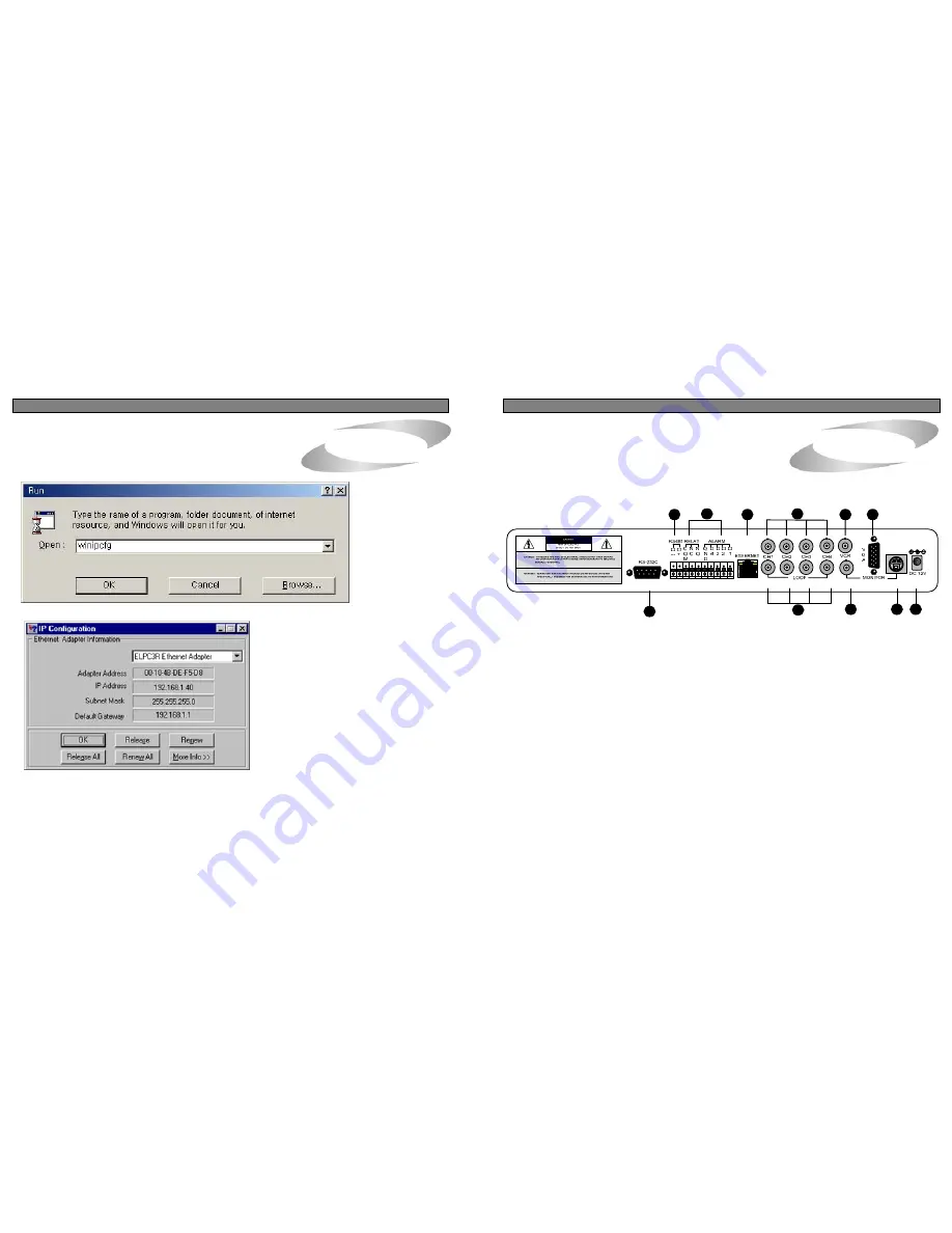
2. RearPanel
2. RearPanel
3.Unit Description
When winipcfg launches, you’ll get a window like this one.
b) Confirm if IP Address is working by executing pingtest
Execute pingtest with IP Address which you assigned to DVMR unit, check if it is successful before you try
to access to DVMR unit via IP network. If it is not successful, you may not be able to access to DVMR unit
via IP network, and we recommend you to get help from your network administrator.
4. Insertion of logo in live window and scan window
You can insert logo of your company in live window and scan window, if you want.
When you install our client program, it automatically create folder named logo under DVMR Remote
Viewer folder. Prepare logo to be inserted in live window in the resolution of 85x55 in bmp format and
in resolution of 165x65 in bmp format, respectively, and put them in logo folder under DVMR Remote
Viewer folder with name of blogo (to be shown in live window) and slogo (to be shown in scan window).
These logos will be shown on the right side of POWER switch in live window and scan window,
respectively. if you do not assign blogo and slogo, no logo will be shown on the right side of POWER
switch.
5. Live view via IP network
Click Remote Viewer icon to view live pictures via IP network. You will see then following window.
Now, hit the "Release" button and then hit "R
enew". If all goes well, you'll get new informat
ion, and it is for your DVMR unit. Write down
this information on separate paper and input
IP Address, Subnet Mask, and Default Gate
way into your DVMR to which you want to ac
cess via IP network.
1
2
3
4
5
7
9
6
8
10
11
1. RS-232C Port Connection
2. PAN/TILT Controller
3. Sensor Input/Output
4. LAN (TCP/IP)
5. Camera Connection
6. LOOP Output
7. VCR Connection
8. MONITOR Connection
9. VGA Connection
10. S-VHS Connection
11. D/C Power Connection
NOTICE : When connecting with other applications, be sure to turn off the system.
Function of each button in live-view window :
①
Power switch
: Press power switch to quit. Before press power switch button, press disconnect button
first.
②
Connect button
: Press connect button to connect to DVMR unit via IP network to see live pictures of
DVMR unit. You will see the same live pictures, which are displayed on monitor of
DVMR unit with a certain time delay depending on transfer rate of IP network.
35
4


