ALL ABOUT IMAGE RECOGNITION & PROCESSING
ALL ABOUT IMAGE RECOGNITION & PROCESSING
7. Manual for Remote
viewer software
3. Unit Description
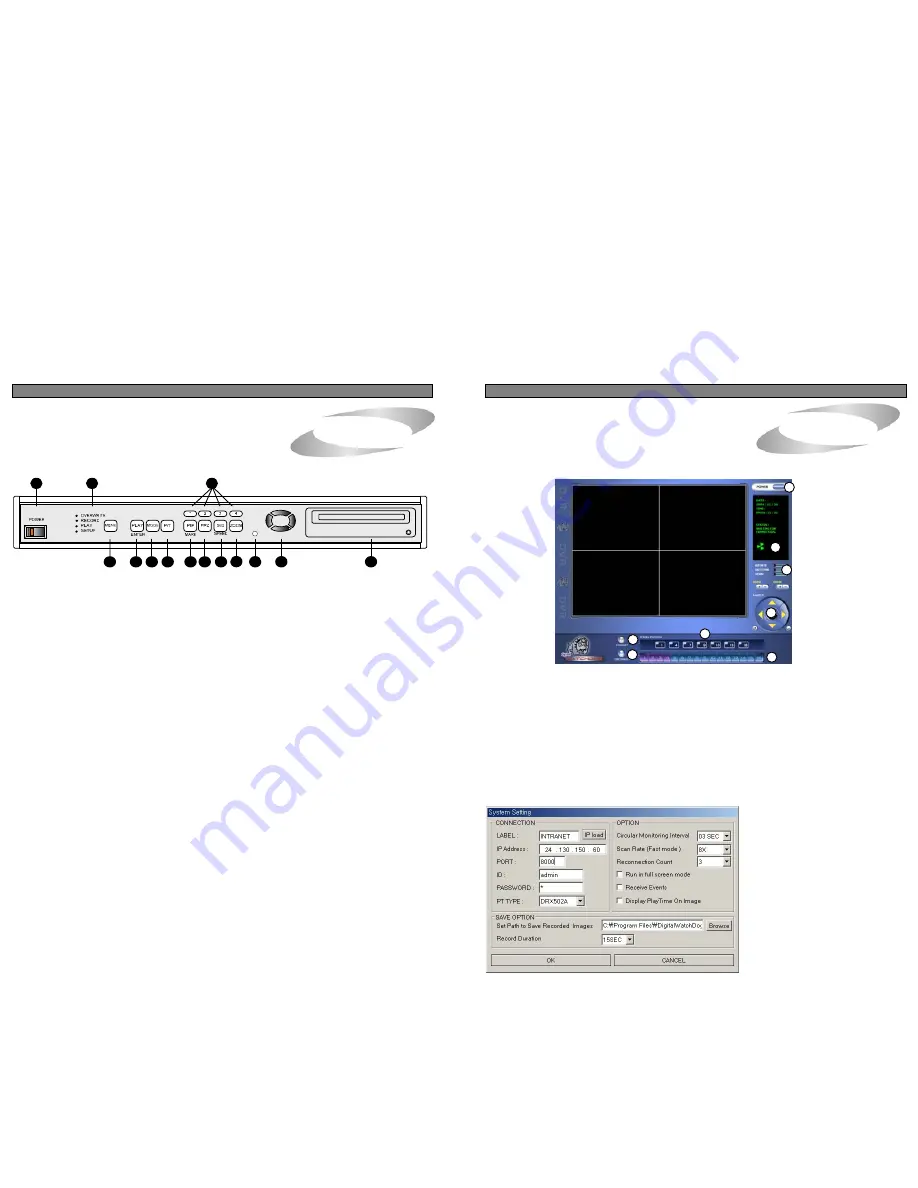
1. Front Panel
1. Front Panel
③
Disconnect button
: Press disconnect button to cut connection to DVMR unit via IP network.
1
13
6
2
3
4
5
7
8
9
11
12
14
10
1. POWER SWITCH WITH LED
: DC power switch with LED
Before you turn off DC power switch off, we strongly recommend you to press
[MENU] button first to make HDD not in writing process.
Generally speaking, cutting power to system may cause trouble in DVMR
system or damage to HDD if HDD is in writing process, and we ask you to
press [MENU] button first to protect HDD from being damaged or system
failure before you press DC power switch off in practical operation.
2. MENU
: Used when changing the menu of SYSTEM SETUP. If you press [MENU] button, recording is stopped.
④
Screen division button
: You can select to see pictures of any single channel or
4channels at the same time. You can select channel number from 1 to 4 to see pictures of selected channel.
If you selected 4, you swill see channel number from 1 to 4 are all activated.
⑤
Channel number button
: You can select channel number to see live pictures from selected channel.
⑥
Status window
: It shows Date and Time. Further it displays “Connection established”
and a circular fan on the left bottom is rotating when connection button is activated, or “Waiting for connection”
when disconnection button is activated
⑦
Set button
: 3 different set buttons
a) Rotate : Press rotate button to see live pictures from channel 1 to 4 in rotation.
Screen division must be set at 1 to see live pictures one after another in
rotation. Speed of rotation shall be as per settings of circular monitoring interval.
b) Setting : It is in the middle of 3 buttons. Press this button to input IP Address and others and to set circular
monitoring interval and scan rate, as following dialog box.
CONNECTION :
- On the LABEL column, you are requested
to input name of 4 ch DVMR units, in case
you want to access to any one DVMR unit
among more than a unit. You can save
many IP information in Configurations
Window and select name of DVMR unit to
which you want to access.
1
6
7
8
5
4
3
2
3. PLAY/ENTER :
Starts playback, and in some functions, it is used as the SELECT key.
4. MODE
: Changes to quarterly split screen or Full display screen.
5. P/T
: Manages PAN/TILT CONTROLLER.
6. 1,2,3,4 :
Chooses each indicated camera.
7. PIP/MARK :
Assigns PIP (Picture in picture) or MARK IMAGE to protect selected image from being
overwritten.
8. FRZ :
Display screen is paused.
9. SEQ/SPEED :
The display screen automatically rotates, and assigns playback speed and direction.
10. ZOOM :
Enlarges the display screen by 200%
11.
Remote Controller Sensor Input Window
12.
Direction button
13. LED Lamps
: Represent status of operation
14. CD-RW DRIVE
NOTICE :
If the Input window (IR receiver) is covered, the remote controller may not work.
NOTICE :
If several buttons are simultaneously or incorrectly pressed, the system may not function
properly.
3
36


