ALL ABOUT IMAGE RECOGNITION & PROCESSING
ALL ABOUT IMAGE RECOGNITION & PROCESSING
4. Installation
7. Manual for Remote
viewer software
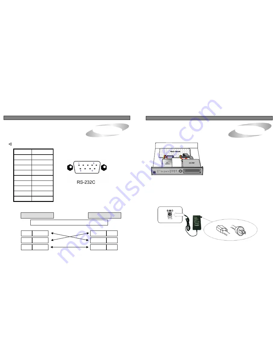
7) HDD connection
4. Arrangement RS-232C pin
RS-232C
Connect main board and HDD using IDE HDD cable and
power cable included in the package.The jumper setting
of HDD must be on Master, as specified by HDD
manufacturer. The jumper setting must be done properly
as specified by HDD manufacturer. Fix HDD on the bottom
of DVMR case using screws included in the package.
Screws must be inserted from outside of the bottom.
And jumper setting of CD-RW DRIVE must be on Slave.
Pin No.
Definition
1
NC
2
RxD
3
TxD
4
NC
5
GND
6
NC
7
NC
8
NC
9
NC
Notice :
Formatting before installation is not required, because DVMR system automatically detects
HDD and formats. In the first operation after installation of HDD, first set at FACTORY DEFAULT
in setup menu and then do HDD CLEAR in SETUP menu of DVMR system.
8) Power Connection
Connect the power to the POWER CONNECTION on the Rear Panel of the system, and turn on the switch.
DVMR unit
Other device (PC)
D-SUB 9 cable (
twisted RS-232C cable)
# 2
RxD
# 2
RxD
# 3
TxD
# 5
GND
# 3
TxD
# 5
GND
Notice :
To turn off DC power switch on the front panel of DVMR case, be sure to press [MENU] button
first. If you press [MENU] button, DVMR system stops recording, and you can cut power to DVMR unit
while HDD head is not in writing mode. It is necessary to press [MENU] button first and turn DC power
switch off to protect HDD head from being damaged and eliminate possibility of mal-function of DVMR
unit.
9) Turn on the POWER and Log-in to the system
Follow direction in the Log-in part of this manual to input the PASSWORD and start the system.
Factory default password for account manager is “1”, for user “2”
10) Detail setup in SYSTEM SETUP
For detail setup, refer to the instruction of SYSTEM SETUP.
31
8


