Physical Description
Table 2–1
DC Power Connector (±5 V/±12 V) Pin-Out (J33)
Pin Number
Function
1
POWER GOOD
2
+5 V
3
+12 V
4
-12 V
5
Ground
6
Ground
7
Ground
8
Ground
9
-5 V
10
+5 V
11
+5 V
12
+5 V
Table 2–2 lists the pins and functions of the dc power connector (J34).
Table 2–2
DC Power Connector (+3.3 V) Pin-Out (J34)
Pin Number
Function
1
Ground
2
Ground
3
Ground
4
PCI +3.3 V
5
PCI +3.3 V
6
PCI +3.3 V
7
PCI +3.3 V
8
PCI +3.3 V
9
PCI +3.3 V
10
Ground
11
Ground
12
Ground
2.2.2.2
Engineering and Manufacturing Test Connector (J32)
The engineering and manufacturing test connector (J32) is a 10-position
(2 x 5) connector for Digital engineering and manufacturing use only; DO
NOT CONNECT.
2–6
Содержание AXPpci 33
Страница 10: ......
Страница 14: ......
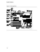
Страница 18: ...System Summary Figure 1 1 Main Logic Board MR 6391 AI 1 4...
Страница 22: ...Physical Description Figure 2 2 MLB Mechanical Drawing MR 6414 AI 2 4...
Страница 23: ...Physical Description Figure 2 3 MLB Component Outline Drawing MR 6401 AI 2 5...
Страница 46: ......
Страница 64: ......
Страница 70: ......
Страница 98: ......


