Physical Description
2.2.2.5
Halt/Reset Switch Connector (J11)
Use the 2-position Halt/Reset switch connector (J11) to attach a normally
open switch for either halting the system or resetting the system,
depending on the select jumper setting. For further information, see
Section 2.2.4.3.
Table 2–5 lists the pins and functions of the Halt/Reset switch connector.
Table 2–5
Halt/Reset Switch Connector Pin-Out (J11)
Pin Number
Function
1
Ground
2
Halt/Reset
Normally open
Figure 2–4 shows the Halt/Reset switch circuit.
Figure 2–4
Halt/Reset Switch Circuit
MR-6413-AI
2.2.2.6
IDE Disk Connector (J18)
The AXPpci 33 supports one IDE compatible interface (J18) for the
Windows NT operating system. This is a 40-position (2 x 20) male-
shrouded keyed connector.
The IDE interface does not currently support the Digital UNIX operating
system.
Table 2–6 lists the pin numbers and functions of the IDE disk connector.
Table 2–6
IDE Disk Connector Pin-Out (J18)
Pin
Number
Function
Pin
Number
Function
1
Reset
2
Ground
3
Data 7
4
Data 8
5
Data 6
6
Data 9
2–8
Содержание AXPpci 33
Страница 10: ......
Страница 14: ......
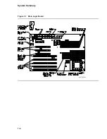
Страница 18: ...System Summary Figure 1 1 Main Logic Board MR 6391 AI 1 4...
Страница 22: ...Physical Description Figure 2 2 MLB Mechanical Drawing MR 6414 AI 2 4...
Страница 23: ...Physical Description Figure 2 3 MLB Component Outline Drawing MR 6401 AI 2 5...
Страница 46: ......
Страница 64: ......
Страница 70: ......
Страница 98: ......


