Physical Description
Figure 2–5
Keylock and Power LED Circuit
MR-6408-AI
2.2.2.10
LED Display Connector (J6)
The 16-position (2 x 8) LED display connector (J6) supplies power and
signals to an optional circuit board (system integrator provided) with
8 LEDs. The LEDs light with various codes to show the state of the
boot and power-up-self-test (POST) diagnostic firmware. The LEDs show
the results of writes to the lowest 8 bits of any address in the range
0.3880.0000 through 0.38ff.ffff. For consistency, it is recommended that
address 0.3880.0000 be used. At the successful conclusion of self-test, the
resulting code shows the cache size detected.
Use the LED ENABLE L signal to enable an 8-bit register chip such as
74F377, and the LEDCLK signal to strobe the 8 bits of data
(Data 0–Data 7) into the register on the rising edge.
Table 2–10 lists the pins and functions of the LED display connector.
2–11
Содержание AXPpci 33
Страница 10: ......
Страница 14: ......
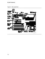
Страница 18: ...System Summary Figure 1 1 Main Logic Board MR 6391 AI 1 4...
Страница 22: ...Physical Description Figure 2 2 MLB Mechanical Drawing MR 6414 AI 2 4...
Страница 23: ...Physical Description Figure 2 3 MLB Component Outline Drawing MR 6401 AI 2 5...
Страница 46: ......
Страница 64: ......
Страница 70: ......
Страница 98: ......


